
 Nederlands

Belt & Auger Scales
The success of a project involving belt scales and auger scales is, of course, determined by the correct choice of scale type. But just as important is the design of the belt or auger itself. For belt weighing, the installation location is important; the angle of inclination, the feed hopper, the belt length, the choice of belt type, the belt speed, the spacing between trough sets, and many other factors all have a significant impact on the weighing result. An incorrect choice regarding any of these factors can have a detrimental effect on accuracy or may even cause the project to fail.
That is why it is of the utmost importance to contact us early in the project so that we can provide key advice before decisions regarding the installation are made. We are here to help you with that.
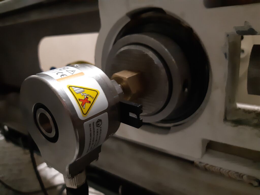
Belt scales and auger scales are used to measure flow rates and volumes. We supply weighing systems for both existing and completely new installations. If desired, we can include the conveyor belt or weighing auger in the delivery. We offer seven different belt scales in our product line; the choice of model depends on the desired accuracy and the characteristics of your installation. Furthermore, a belt scale and a screw scale consist of a speed sensor and a weighing processor.
You’re about to undertake a belt scale project and you’re wondering: What should I focus on most?
You’re about to undertake an auger scale project and you’re wondering: What should I focus on most?
Read our F.A.Q.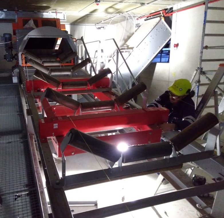
A solution for every dynamic weighing application
Below, we present various models for each category.
BELT SCALE HIGH
HIGH LOAD CAPACITY HIGH SPEEDS
BEST ACCURACY
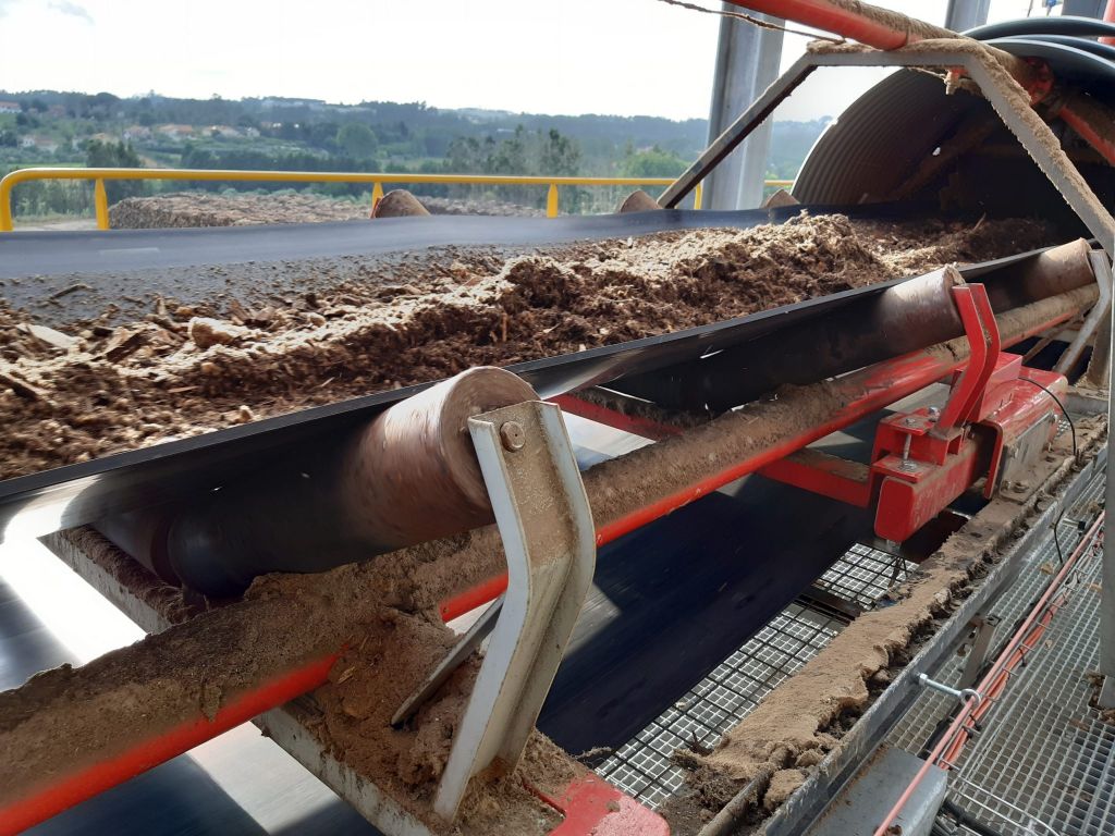
BELT SCALE MID
MODERATE LOAD MODERATE SPEEDS
BELT SCALE LOW
LOW LOAD
LOW SPEEDS
FLAT BELTS
AUGER SCALE
SCREW CONVEYOR
OR
DRAG CHAIN CONVEYOR
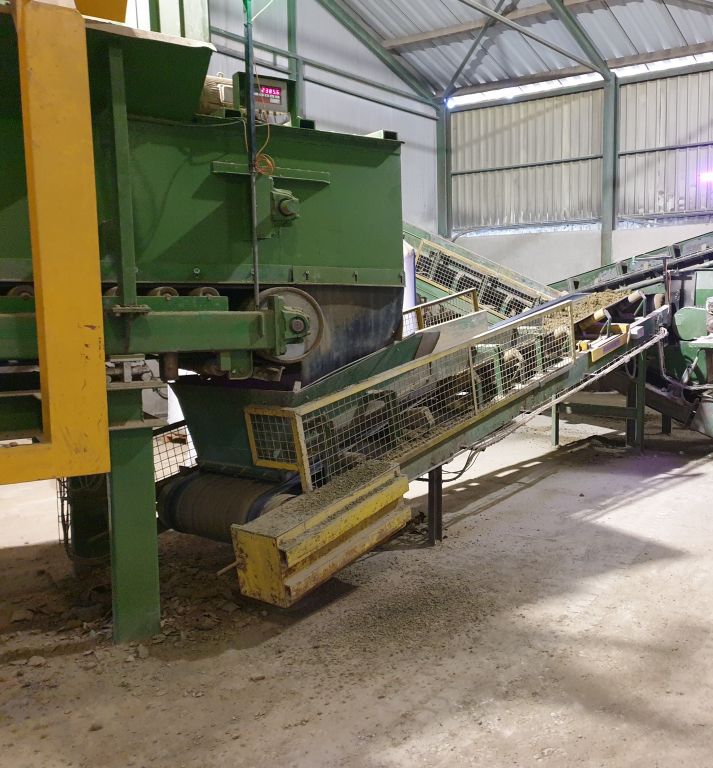
DOSING
WITH WEIGHING BELT
FROM SILO
OR FEEDER
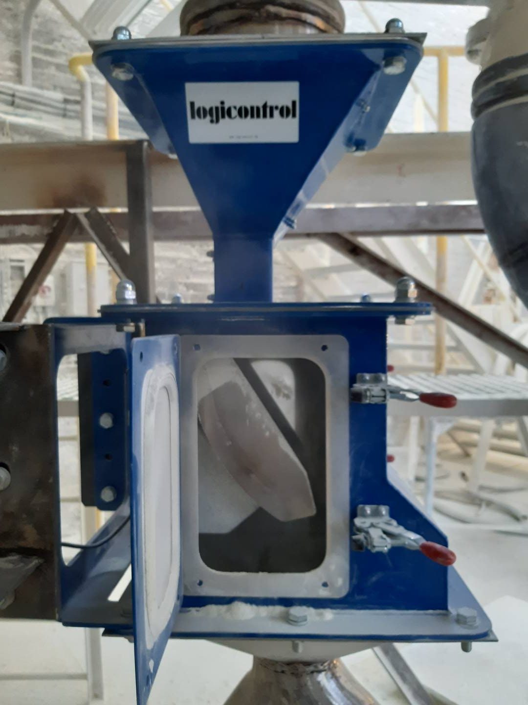
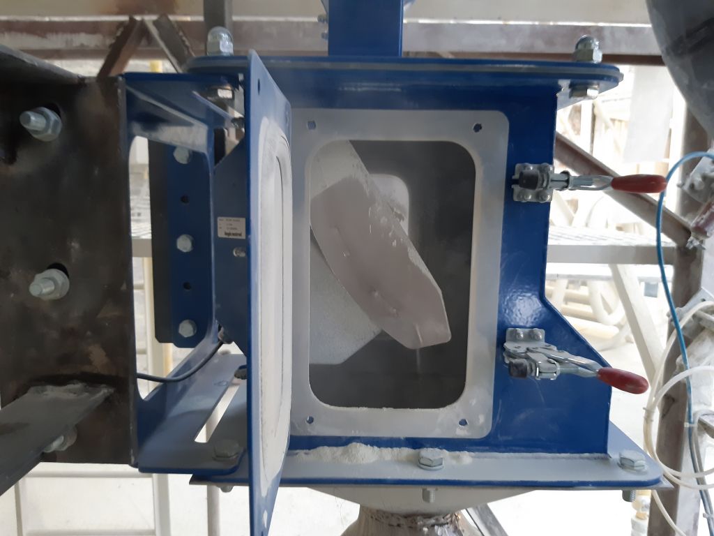
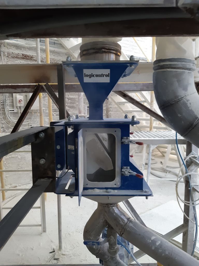
FALLING PLATE FLOW RATE MEASUREMENT
BULK SLIDE PRINCIPLE
BELT SCALE BS 143 High range
HIGH FLOW RATES HIGH LOADS HIGH SPEEDS UTMOST PRECISION
■ 3 (or 2) weigh hoppers
■ Coated steel or 304 stainless steel version
■ Calibrated version available
■ Suitable for flat and inclined conveyors
■ Custom-manufactured
■ Fits into existing installations with minimal modifications
■ INOX IP 67 load cells
■ ATEX version available
■ Accuracy of 0.5% is possible
■ Model offering the highest possible accuracy
■ Flow measurement in aluminum or stainless steel; ATEX-compliant versions available
■ Flow rate and volume measurement
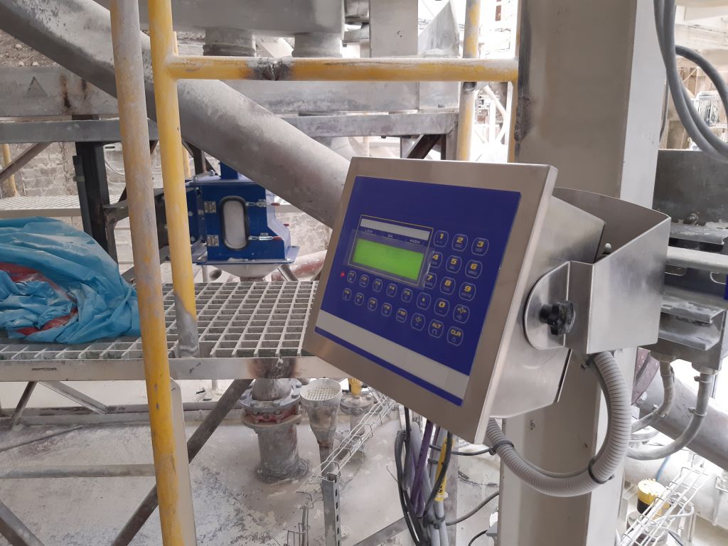
■ Weighing amplifier with IP 67 stainless steel housing
■ Outputs: 4–20 mA, Profinet, Profibus, Ethernet, Modbus, and more
■ Recommended model for loading and unloading ships
■ Ideally suited for very heavy loads, e.g., quarries
Design
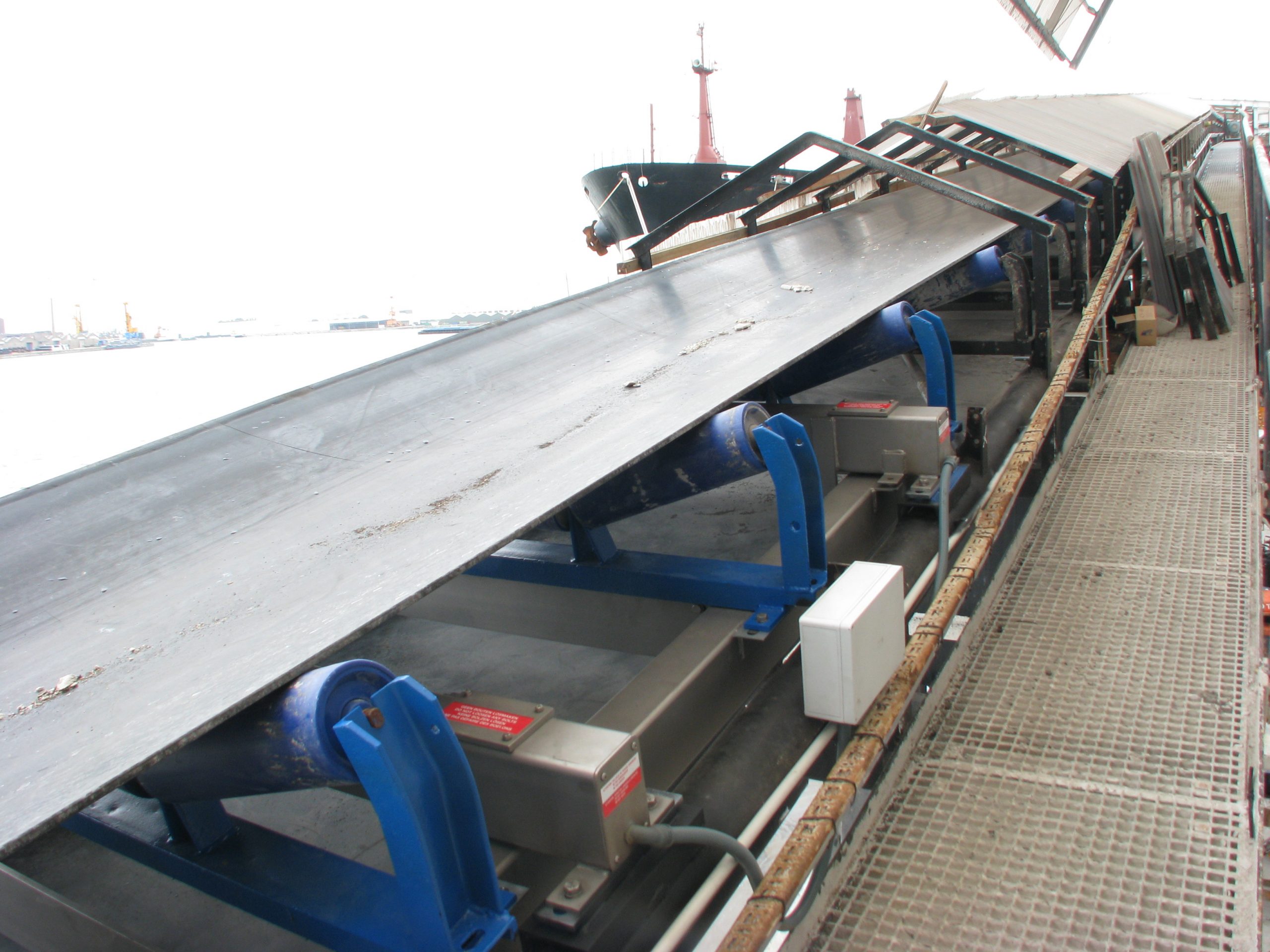
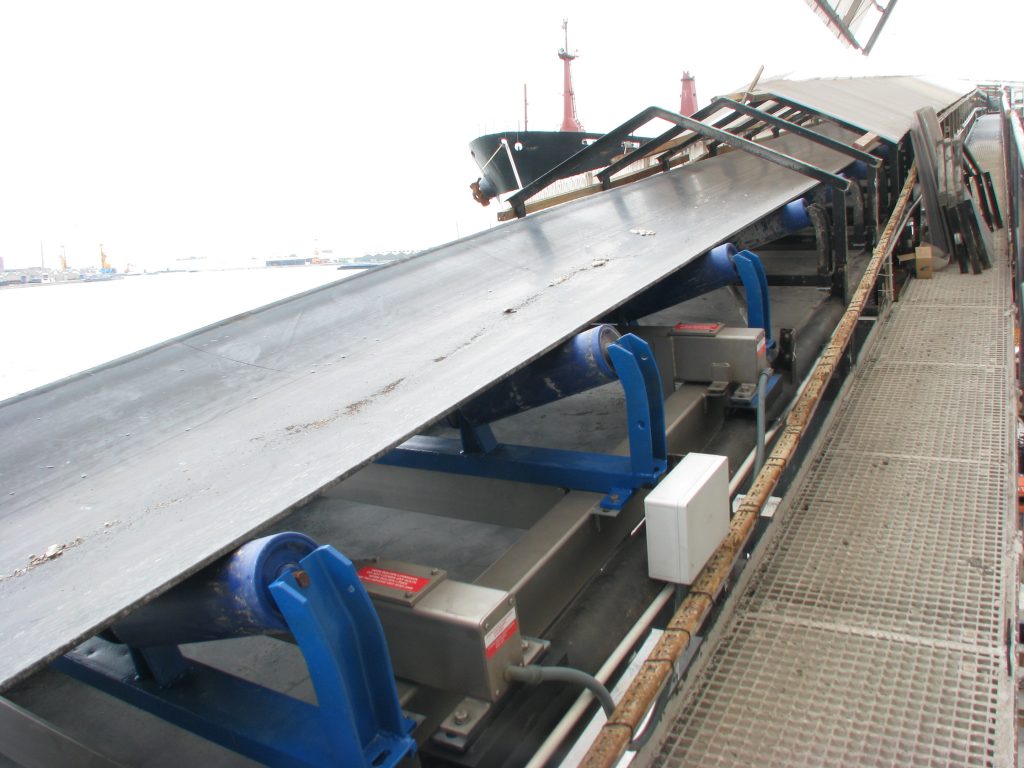
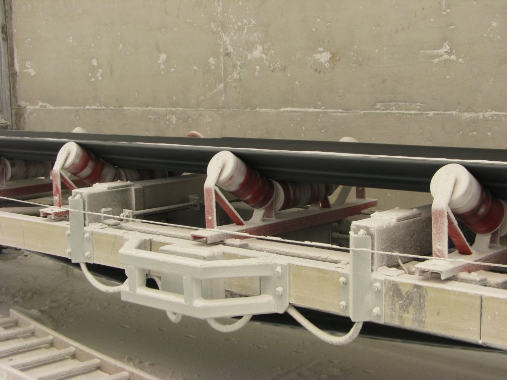
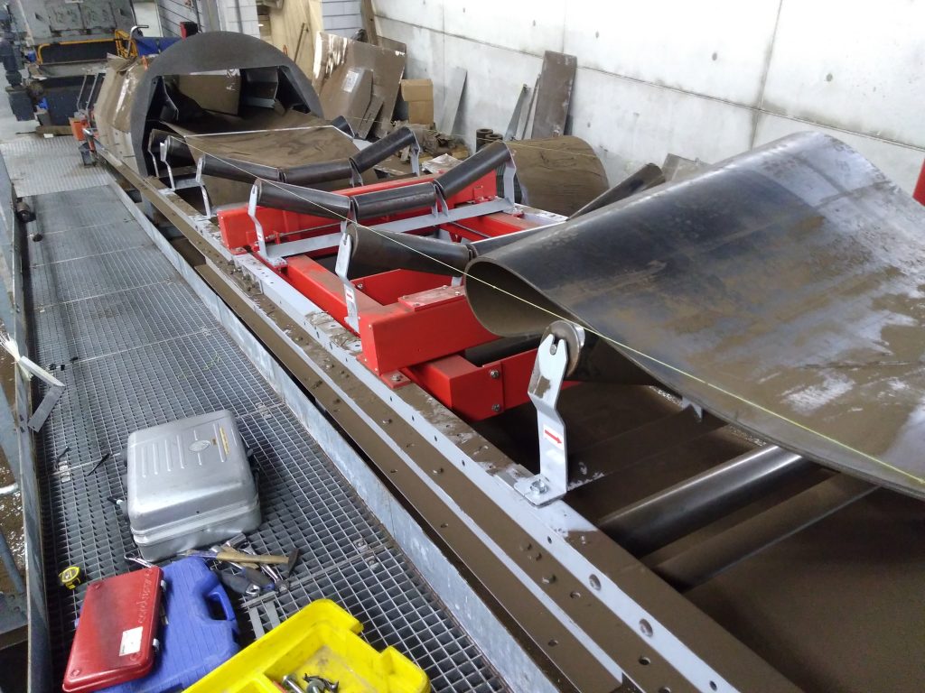
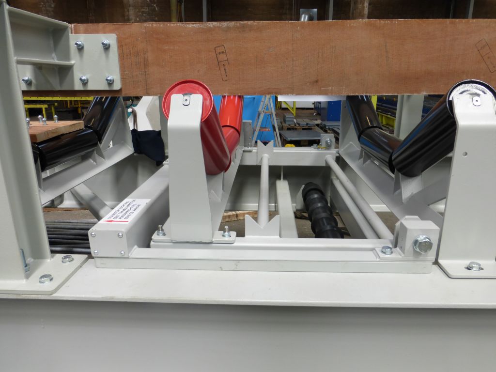
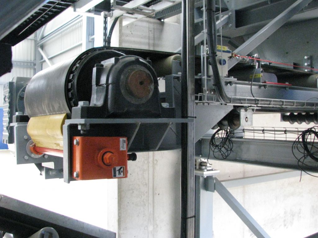
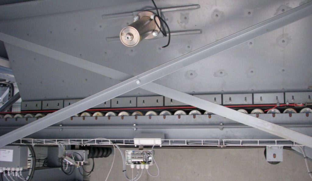
The belt scale consists of two crossbeams mounted on the conveyor belt’s longitudinal beams. Each corner of these crossbeams contains a load cell. A rectangular frame is suspended from these four load cells. Three trough assemblies are mounted on this frame. The load on the three trough assemblies is thus weighed along with the frame by the load cells in the crossbeams. The structure is equipped with stabilizing rods, which keep the suspended frame securely in place, even in an inclined configuration.
By weighing across three trough sections, a long belt length is weighed. This significantly improves the ratio of the weighing section to the variable section. (see our FAQ) This allows for weighing with greater accuracy.
When integrating into an existing belt, at least three trough sections are removed from the system and mounted on the weighing frame.
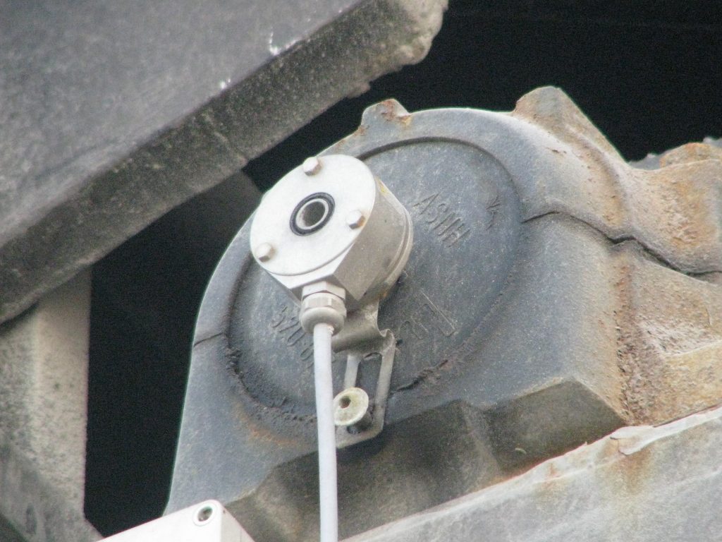
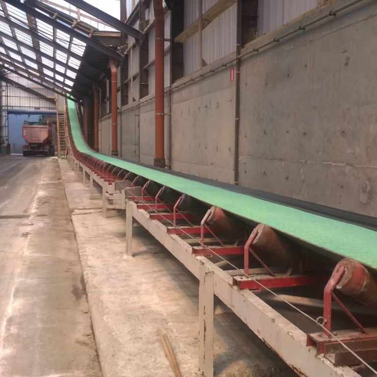
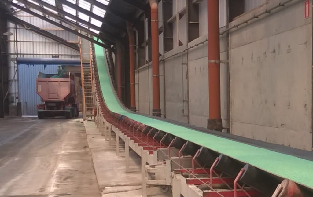
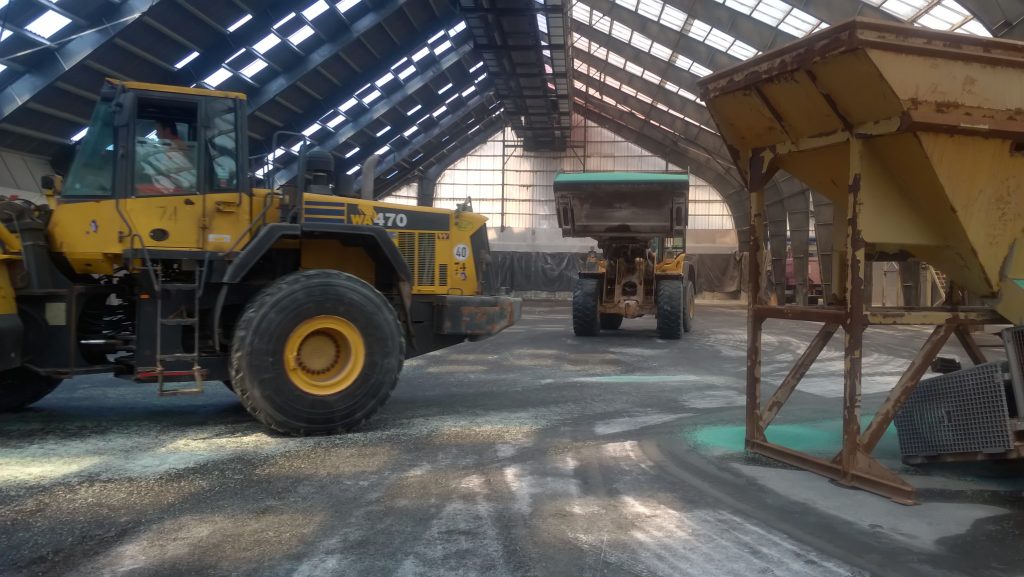
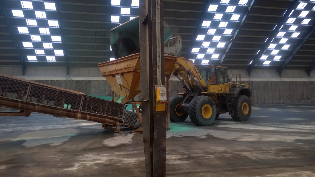
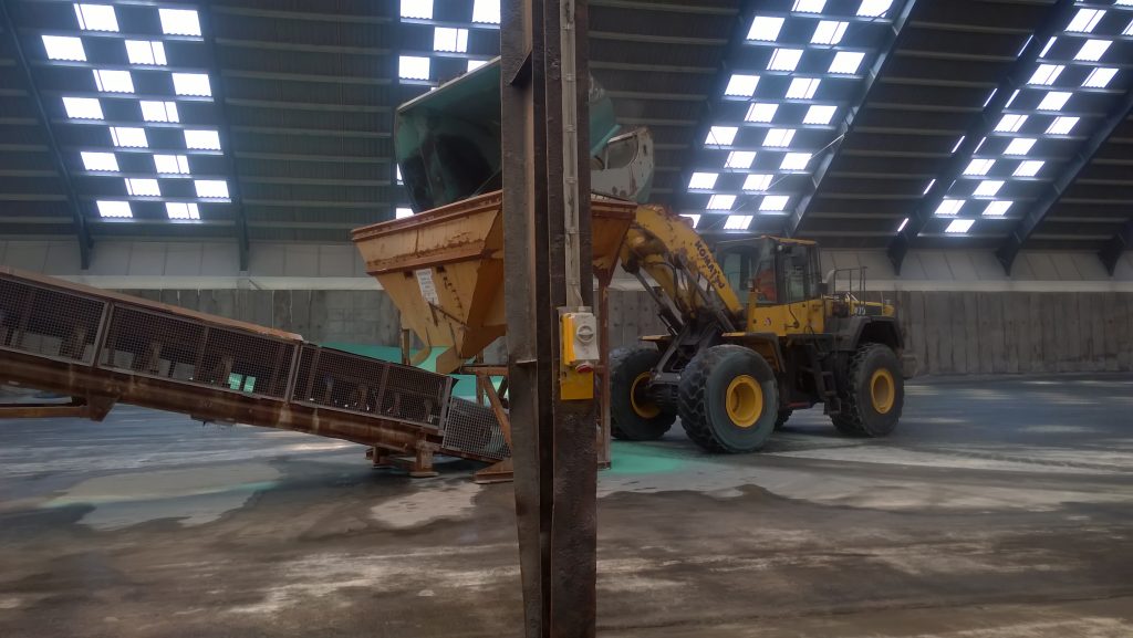
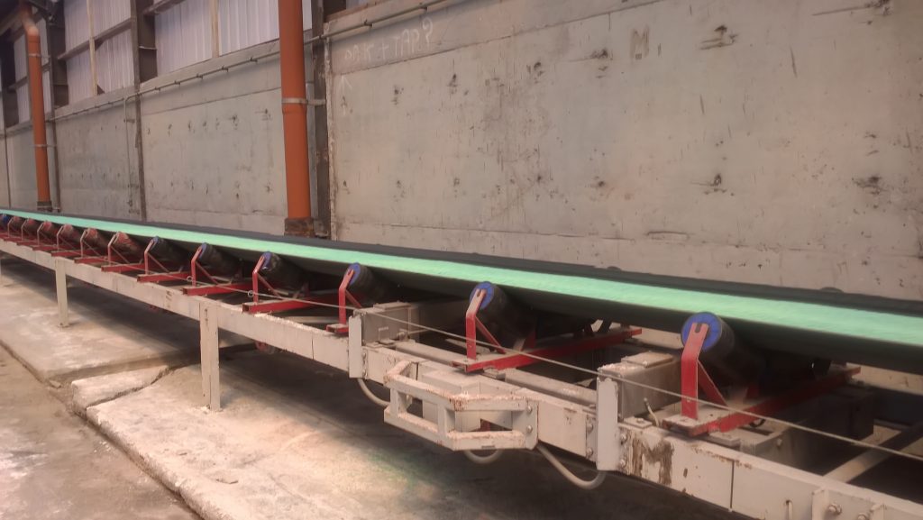
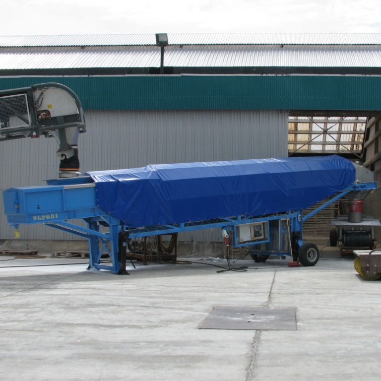
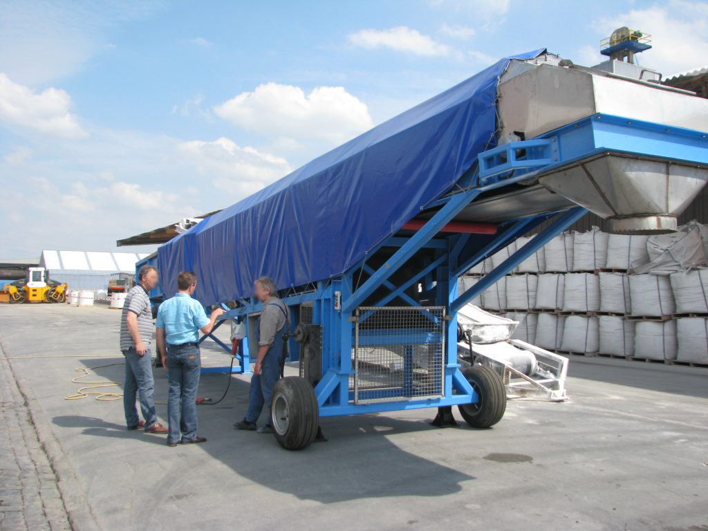
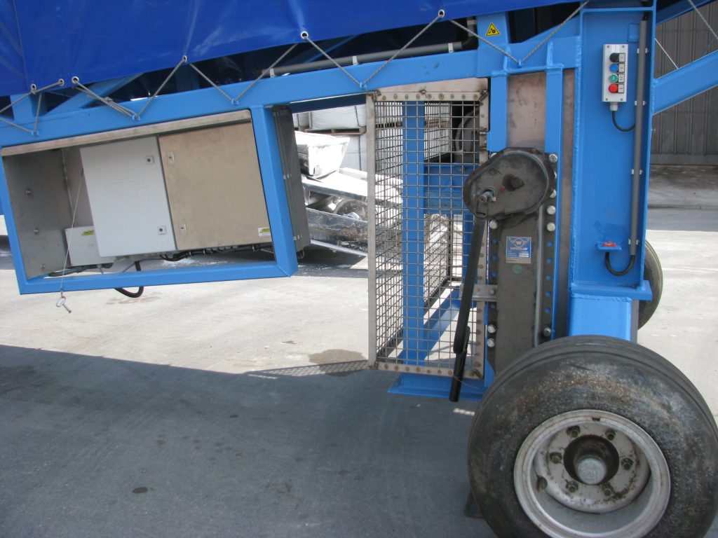
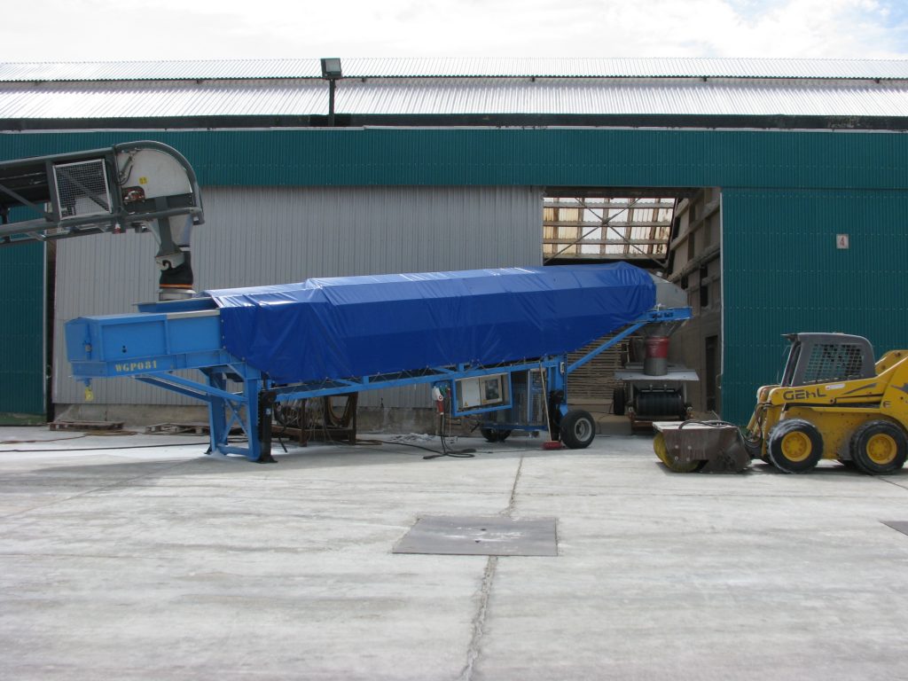
Some of the projects we have completed:

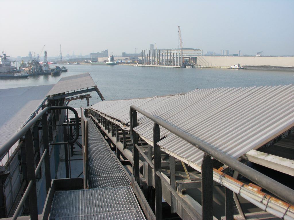
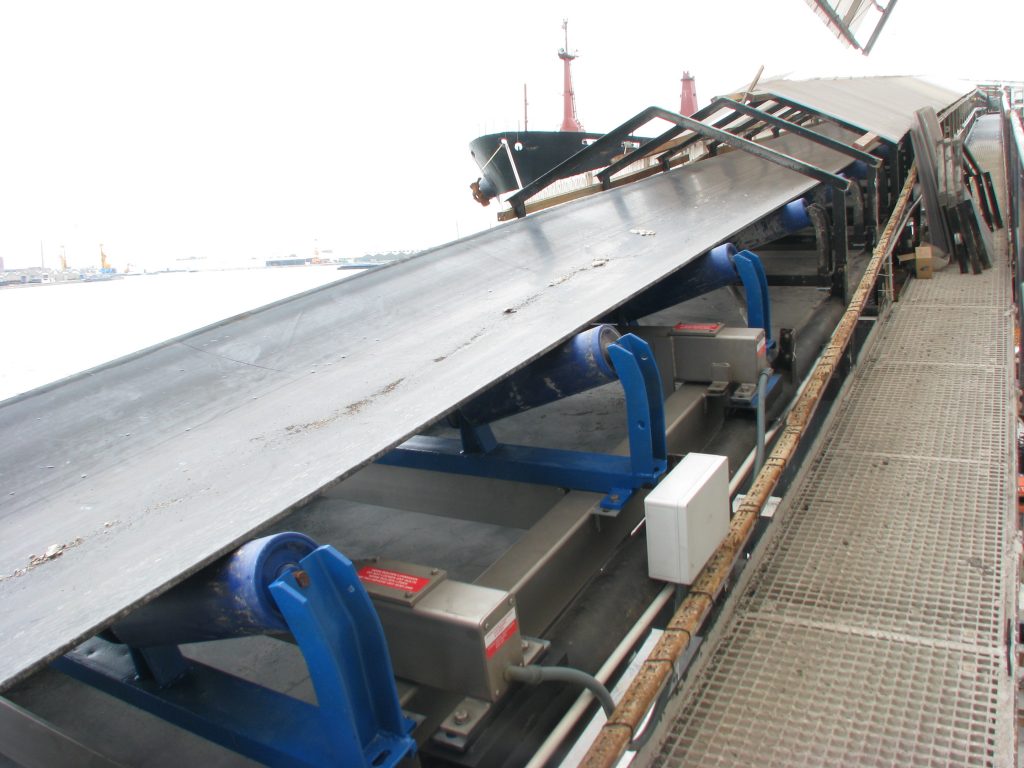
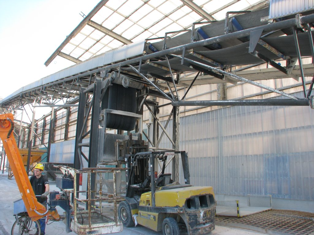
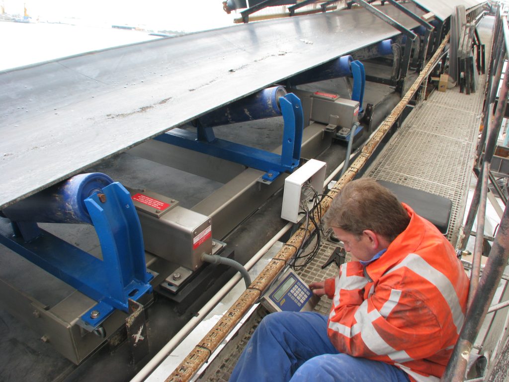



BELT SCALE BS 211 High range
HIGH FLOW RATES HIGH LOADS HIGH SPEEDS
■ 1 set of weighing troughs
■ Coated steel or 304 stainless steel version
■ Suitable for flat and inclined conveyors
■ Custom-manufactured
■ Fits into existing installations with minimal modifications
■ INOX IP 67 load cells
■ ATEX version available
■ Accuracy of 1% is possible
■ Ideally suited for very heavy loads, e.g., quarries
■ Flow measurement in aluminum or stainless steel; ATEX-compliant models available
■ Flow rate and volume measurement
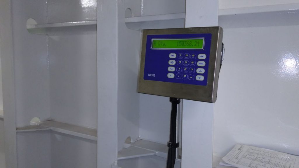
■ Weighing amplifier with IP 67 stainless steel housing
■ Outputs: 4–20 mA, Profinet, Profibus, Ethernet, Modbus, and more
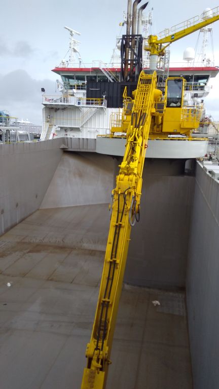
■ Recommended model for loading and unloading ships
Design
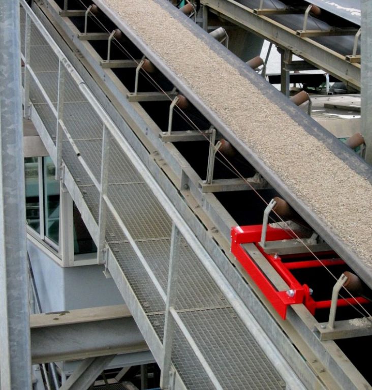
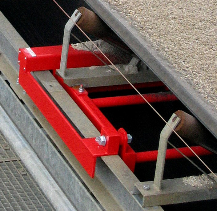
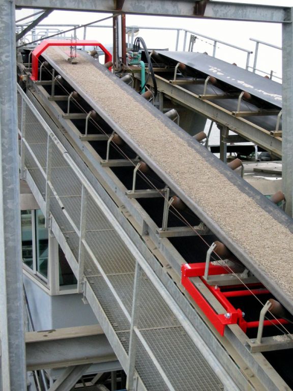
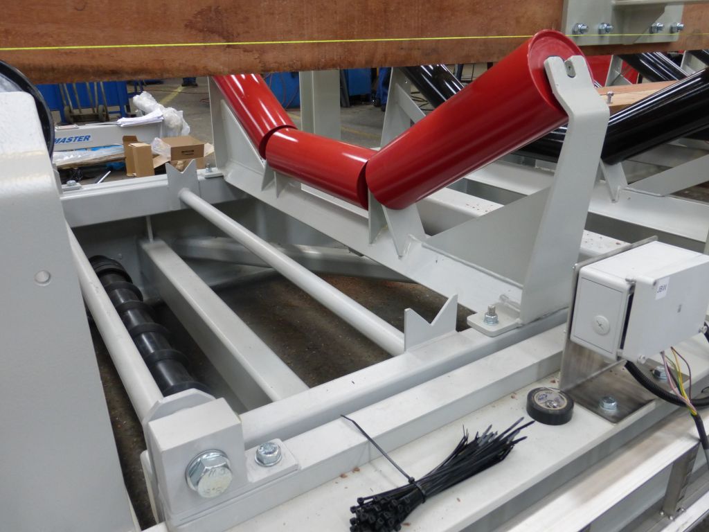
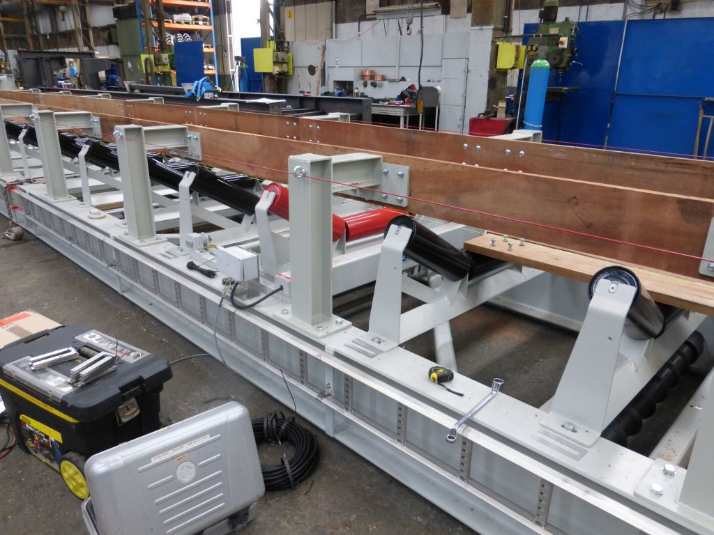
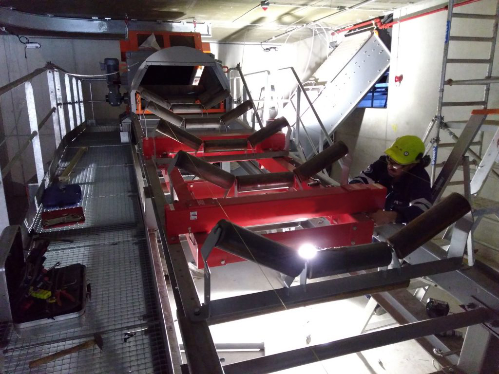
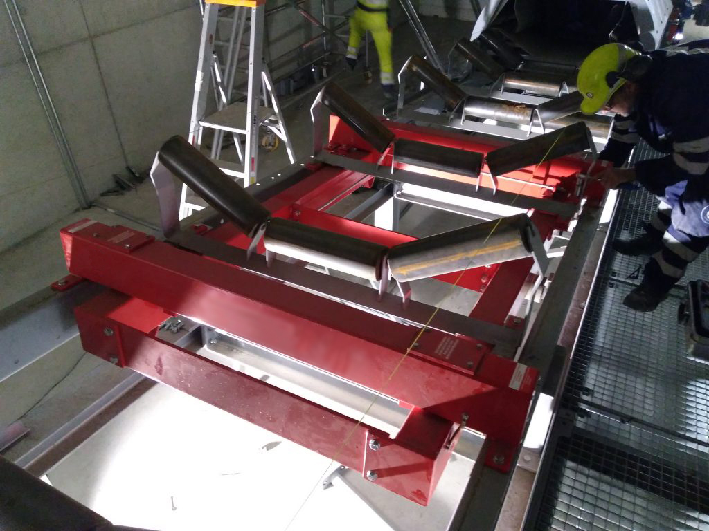
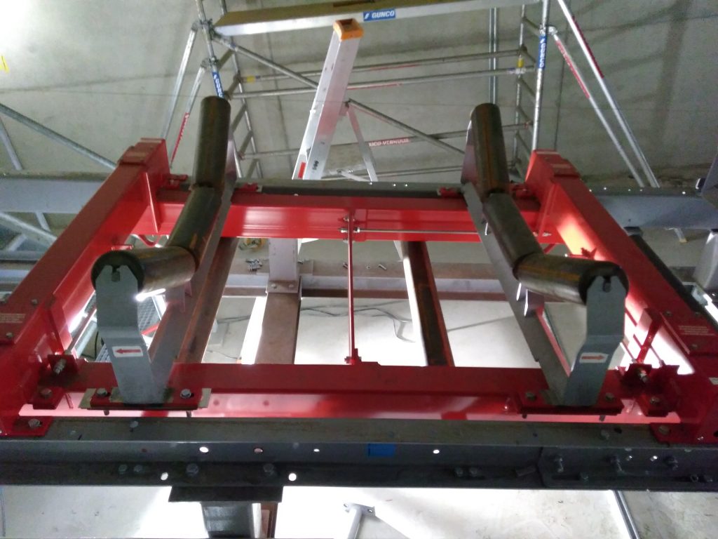
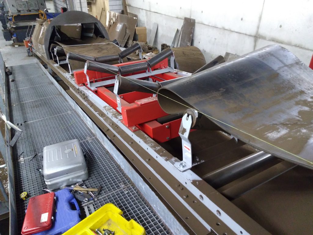
The belt scale consists of a sturdy cradle of a certain length that is suspended at two hinge points. Hinge points are essential for inclined belts and for applications involving heavy loads or high speeds. On the other side, the cradle is suspended from a sturdy frame that spans the conveyor structure and is supported by the conveyor’s beams all the way to the pivot points. The weighing system is integrated into the transverse section, where the cradle is suspended. On the other side, the pivot points are integrated into the arms of the frame.
The forces associated with heavy loads and/or higher speeds should not be underestimated. A belt scale with insufficient rigidity would twist, resulting in inaccurate measurements.
The design of the belt scale ensures a rigid structure. This rigidity is necessary to weigh heavy loads with high accuracy.
When integrating into an existing conveyor belt, one trough set is removed from the system and mounted on the weighing frame.
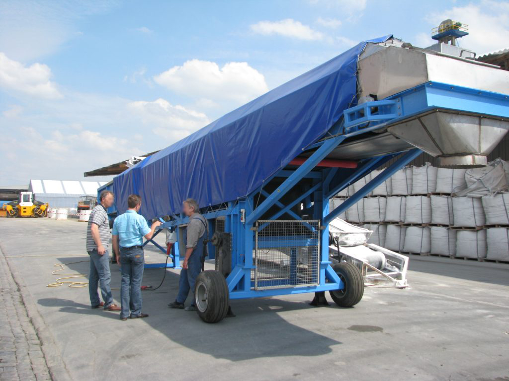
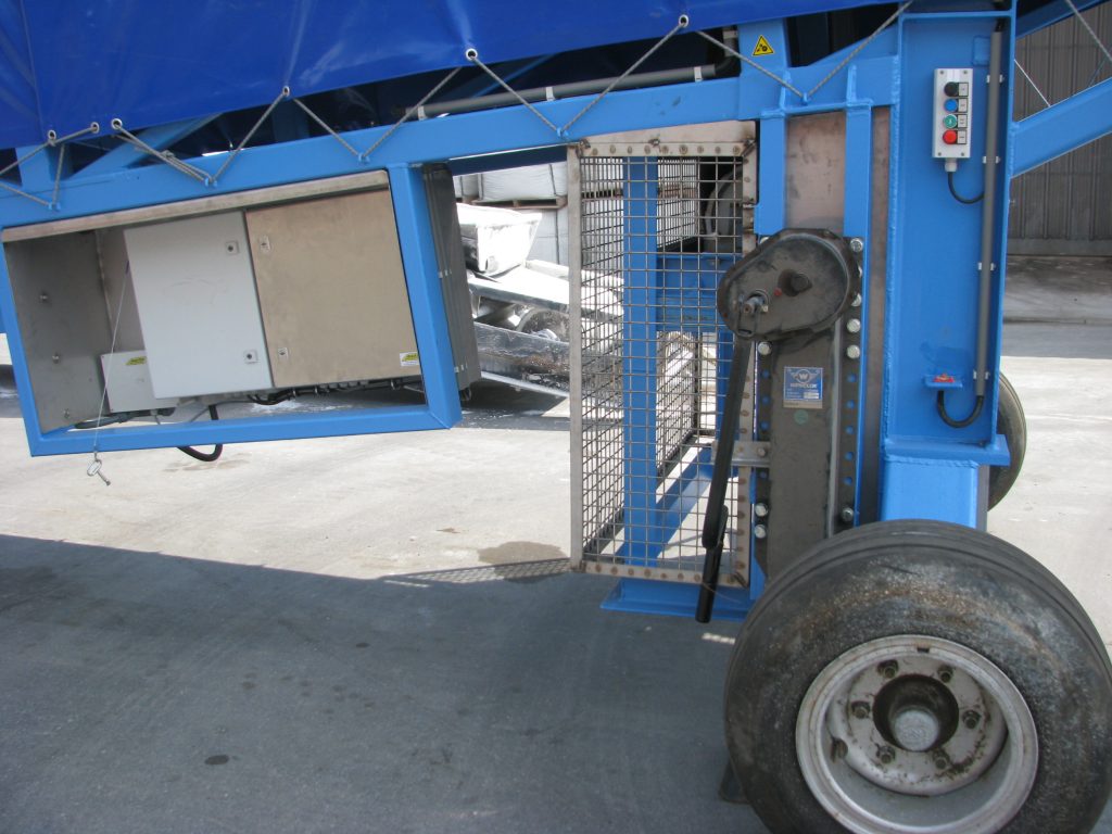
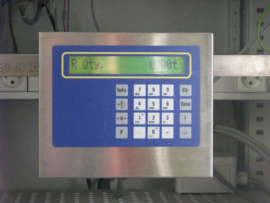
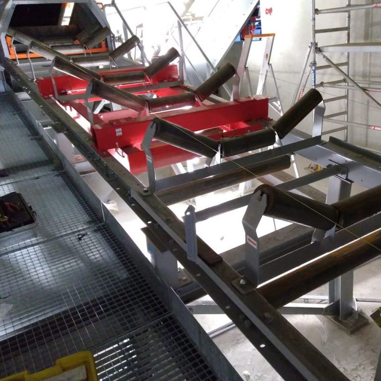
Some of the projects we have completed:




BELT SCALE BS 221 DB Mid range
MEDIUM FLOW RATES UNIVERSAL MODEL FOR ALL BANDWIDTHS
■ 1 weighing trough set
■ Coated steel or 304 stainless steel version
■ Suitable for flat and inclined conveyors
■ Universal model for all belt widths
■ Fits into existing installations with minimal modifications
■ INOX IP 67 load cells
■ ATEX version available
■ Accuracy of 1% is possible
■ Flow measurement in aluminum or stainless steel; ATEX-compliant models available
■ Flow rate and volume measurement
■ Weighing amplifier with IP 67 stainless steel housing
■ Outputs: 4–20 mA, Profinet, Profibus, Ethernet, Modbus, and more
■ Model suitable for medium and low loads
■ Ideal for enclosed structures or for hot products
■ Easy to maintain because the vital components are located on the outside
Design
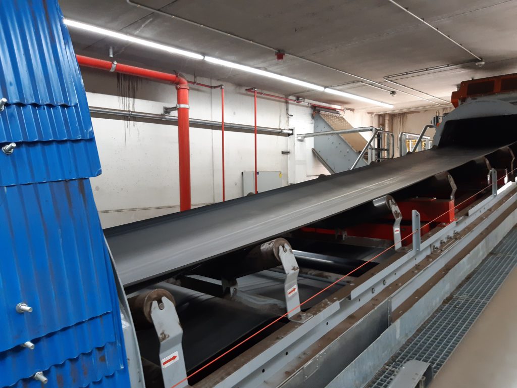
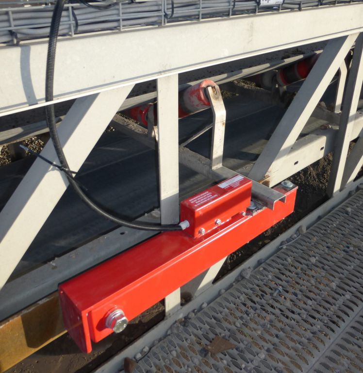
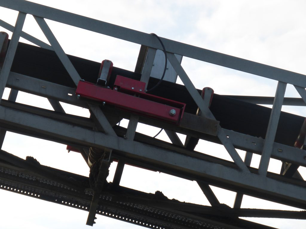
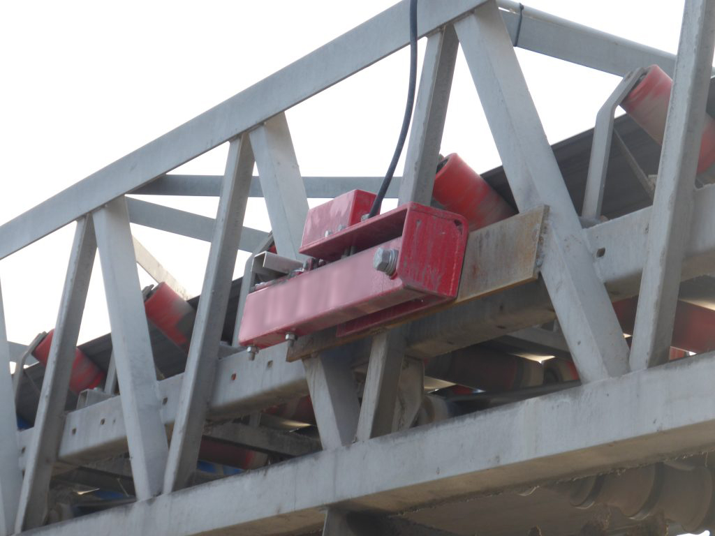
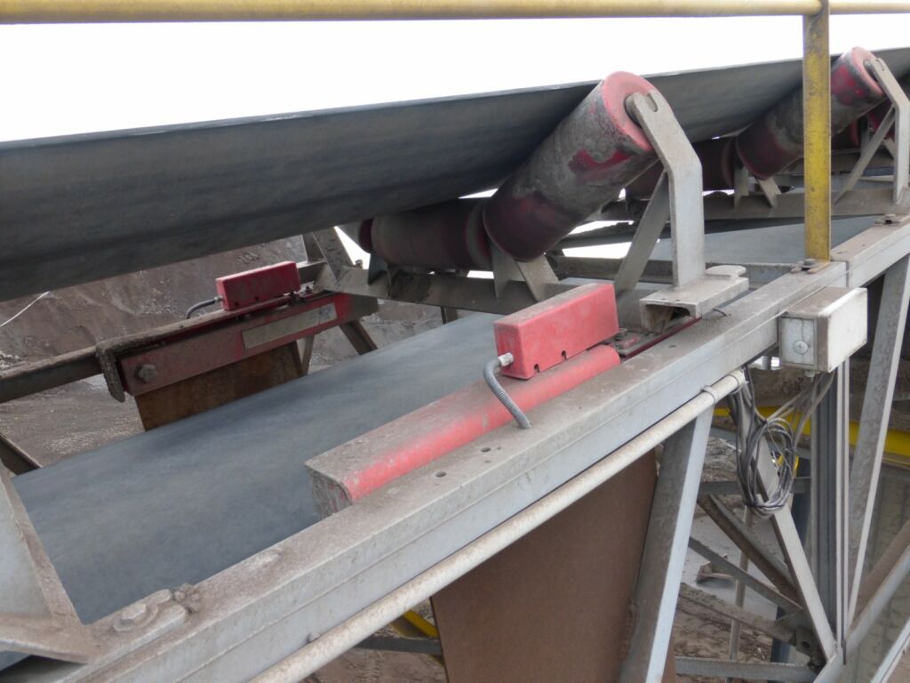
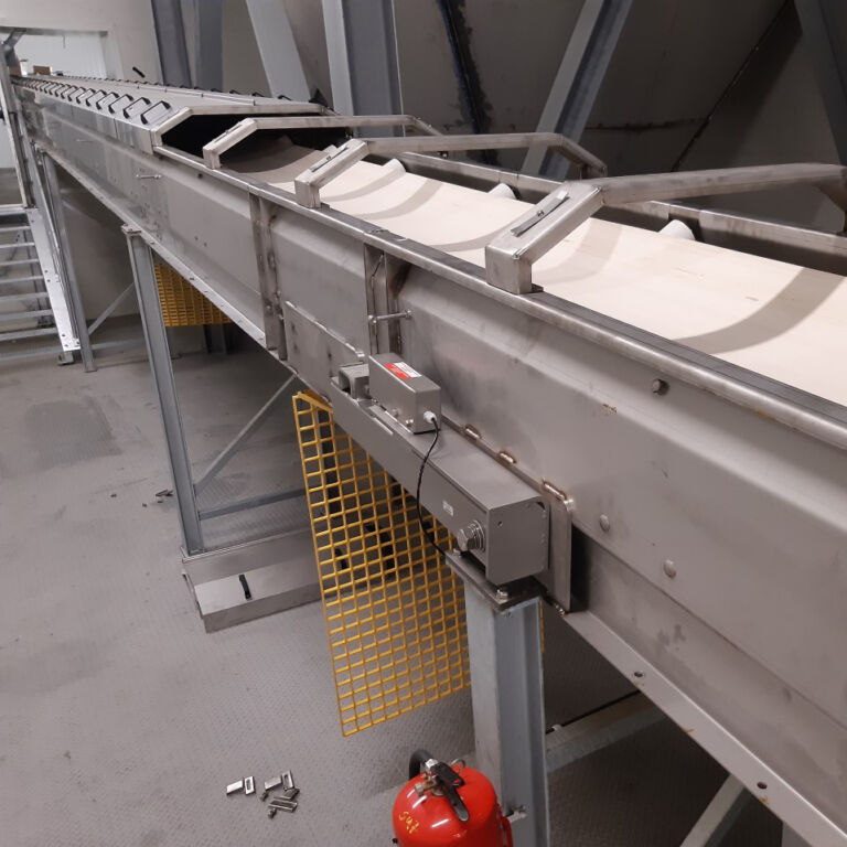
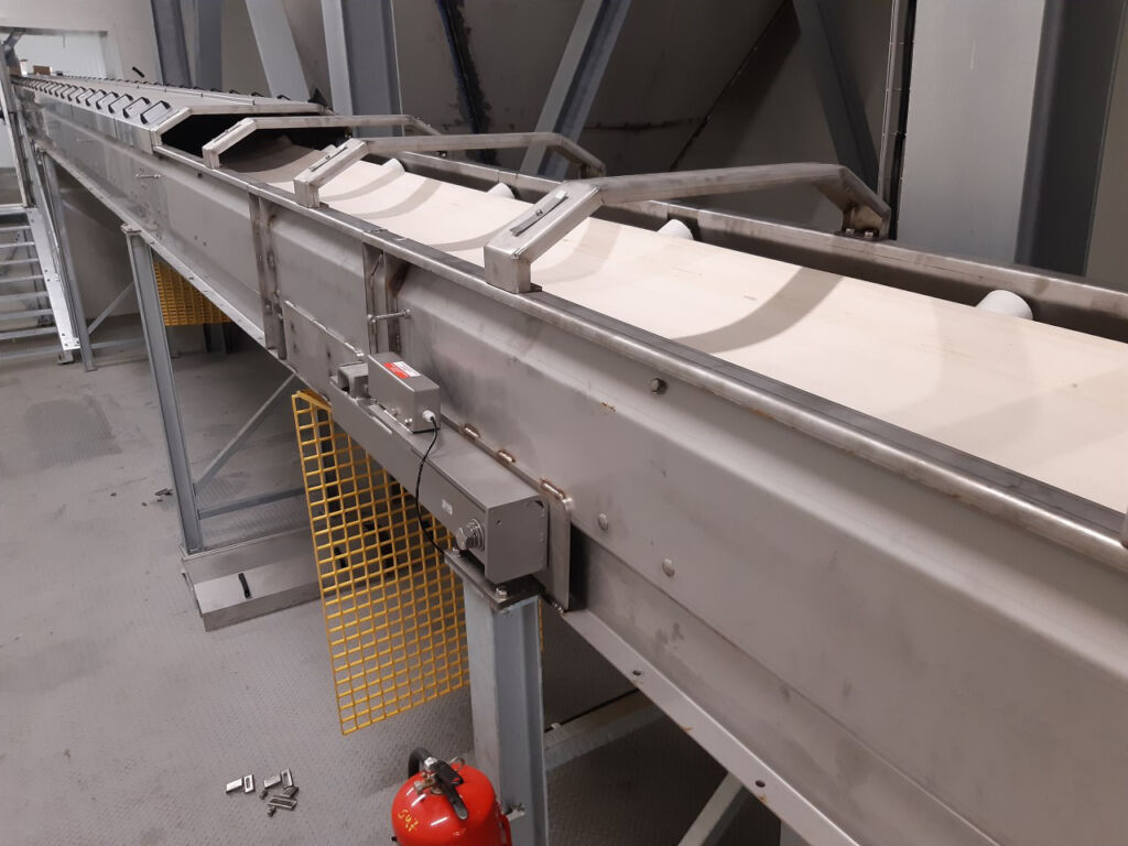
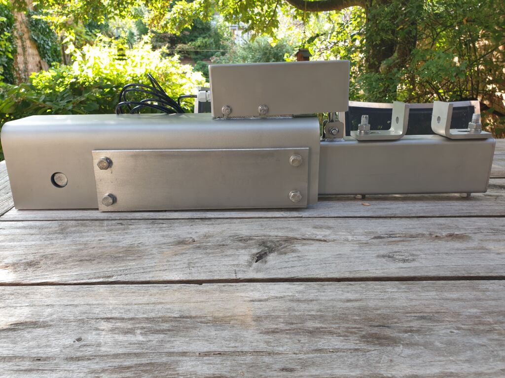
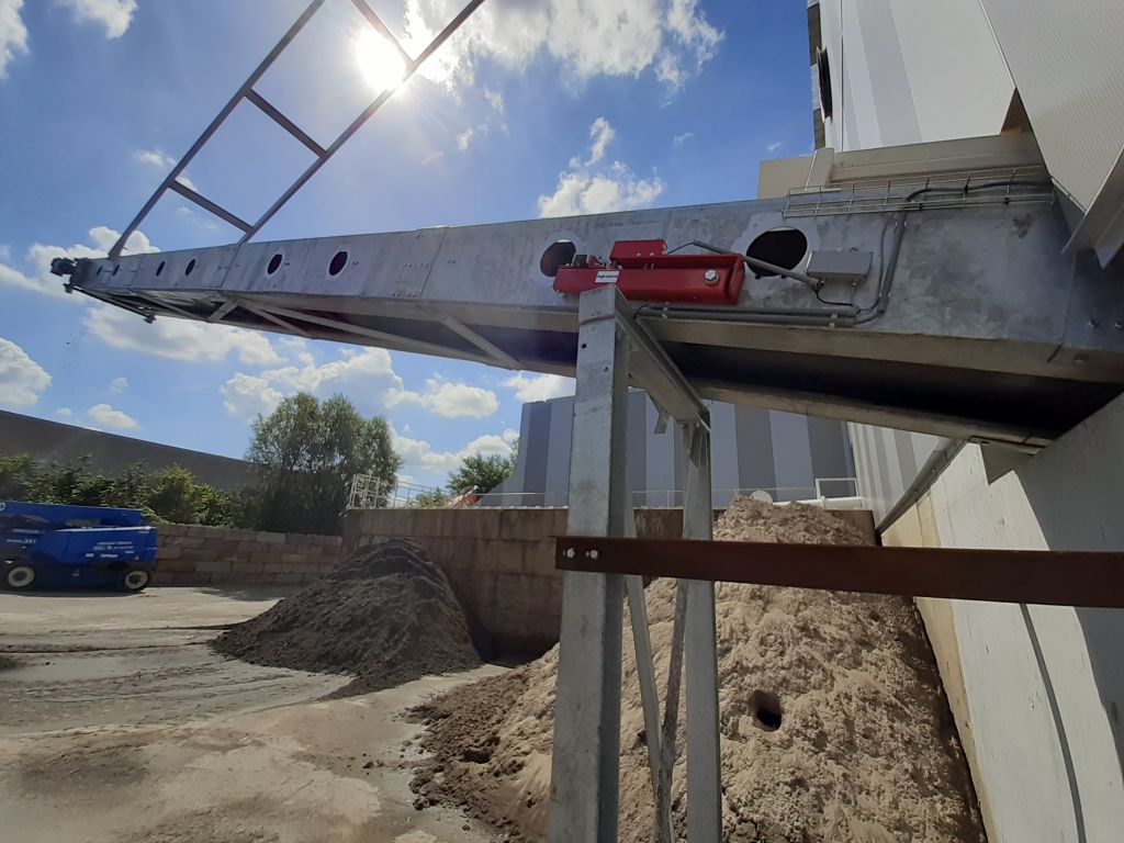
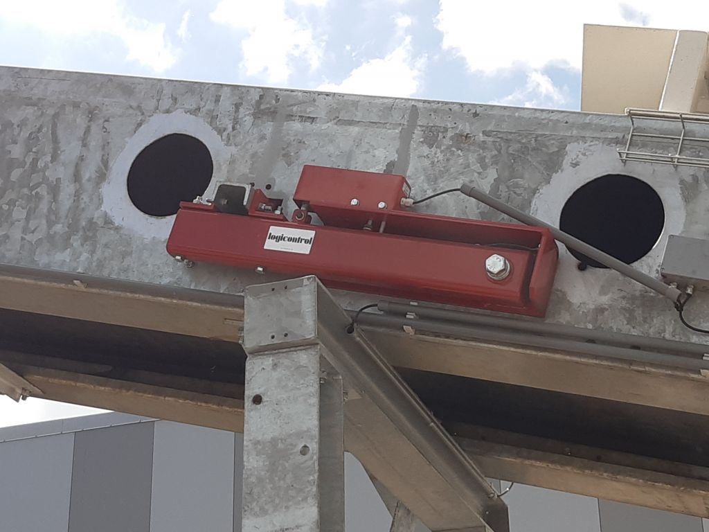
The belt scale consists of two “arms” that are positioned on either side of the conveyor belt. These can be mounted on either the outside or the inside of the structure. Each arm consists of a fixed section that is bolted to the structure. The weighing arm is attached to this fixed section via a pivot point. Midway along the arm, it is suspended from a load cell. A trough assembly is mounted at the end of the arm.
The standard version of the BS221DB is supplied without a trough assembly. Typically, a trough assembly from the existing installation is used, which is the most cost-effective and easiest solution. This results in two setups along both sides of the weighing belt.
The BS 221 DB allows the weighing arms to be mounted along the outside of a closed belt assembly. This is recommended when it is necessary to prevent dust from entering the surrounding area. Furthermore, the weighing system itself is also protected against dust, aggressive products, and high temperatures.

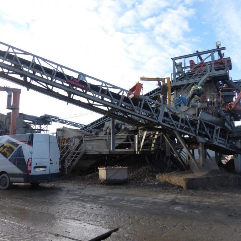
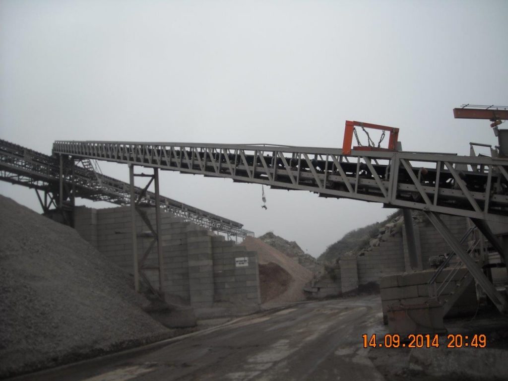
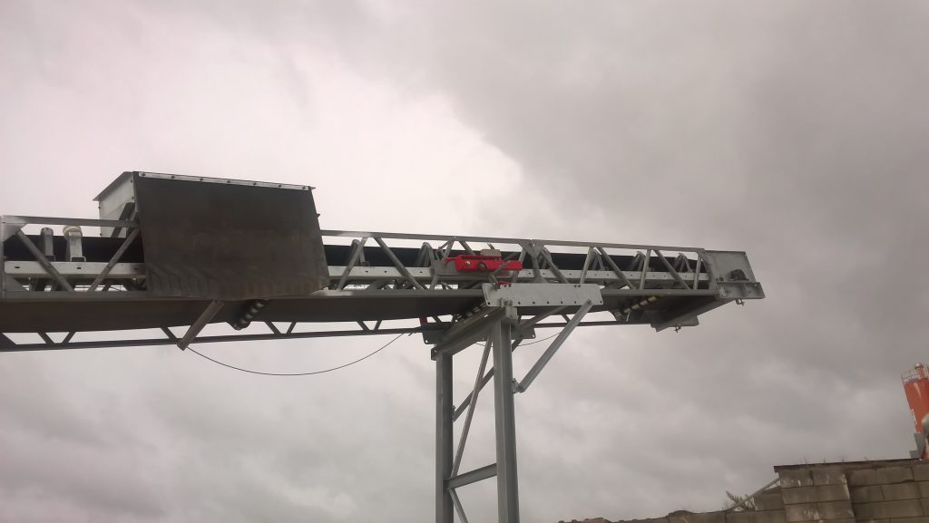
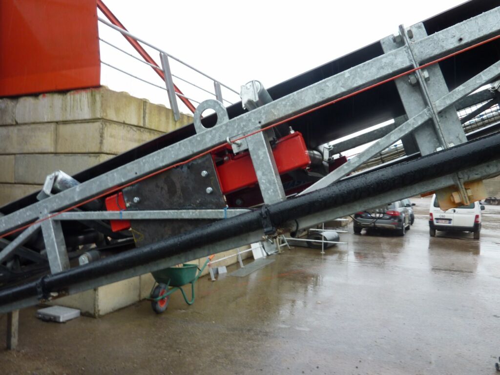
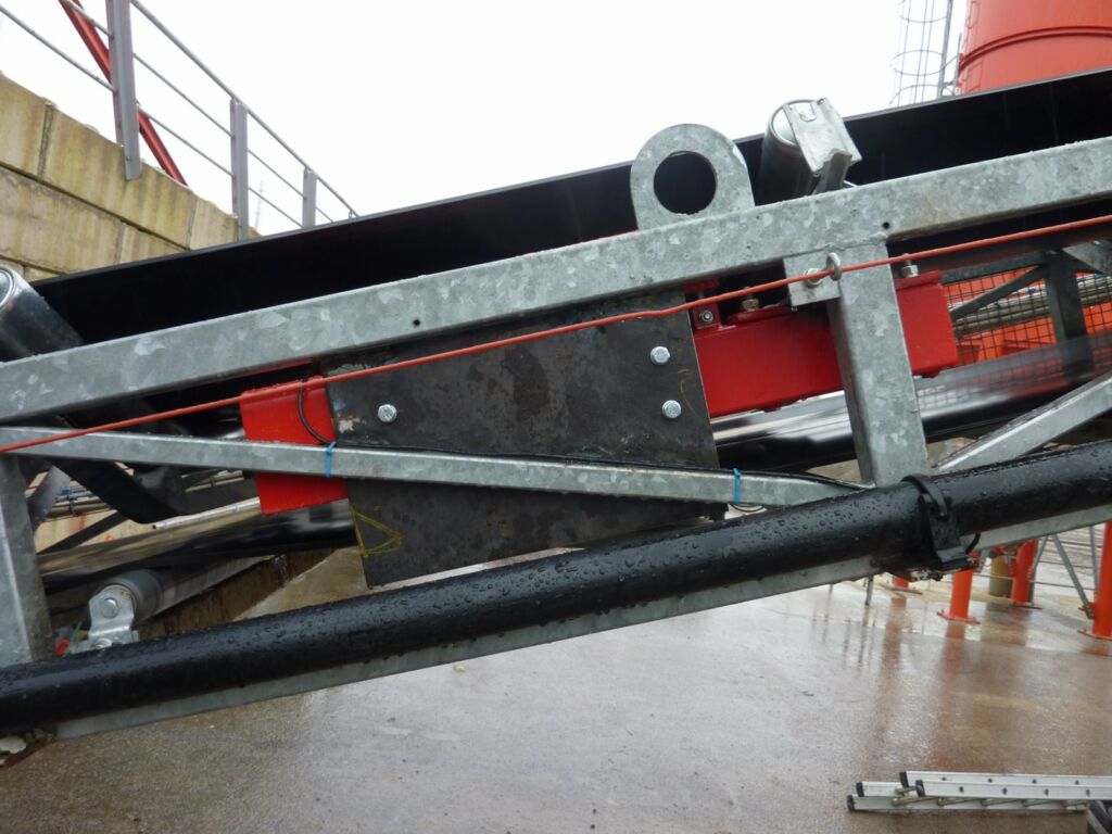
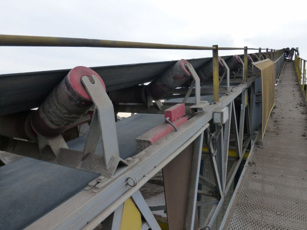
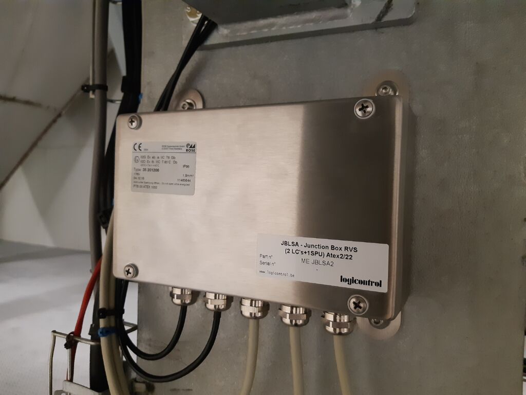
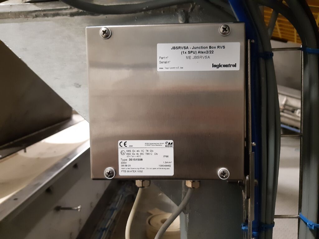
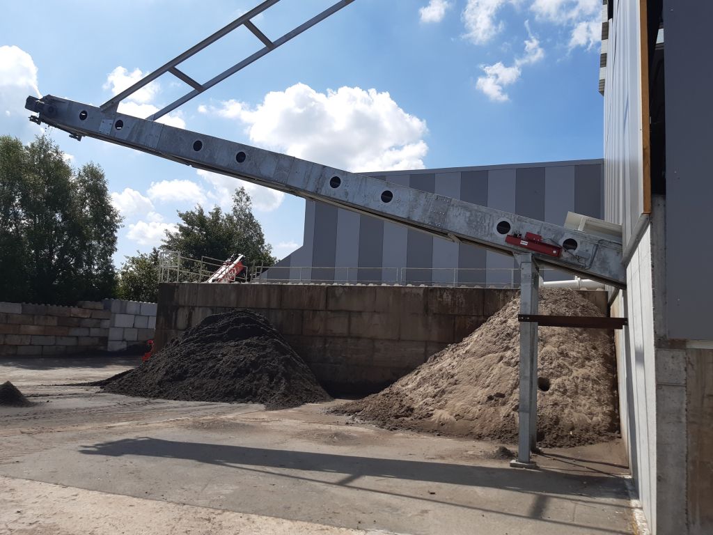
Some of the projects we have completed:




BELT SCALE BS 611 Mid range
MEDIUM FLOW RATES UNIVERSAL MODEL FOR MULTIPLE BANDWIDTHS
■ 1 weighing trough set
■ Coated steel or 304 stainless steel version
■ Suitable for flat and inclined conveyors
■ Universal model for multiple belt widths
■ Fits into existing installations with minimal modifications
■ INOX IP 67 load cells
■ ATEX version available
■ Accuracy of 1% is possible
■ Flow measurement in aluminum or stainless steel; ATEX-compliant models available
■ Flow rate and volume measurement
■ Weighing amplifier with IP 67 stainless steel housing
■ Outputs: 4–20 mA, Profinet, Profibus, Ethernet, Modbus, and more
■ Model suitable for medium and low loads
Design
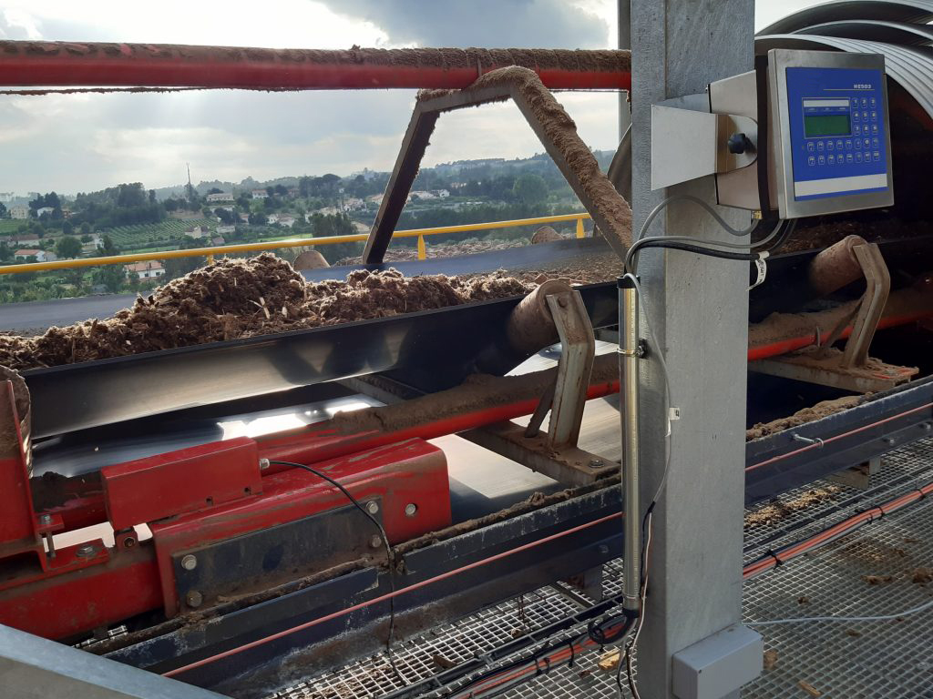
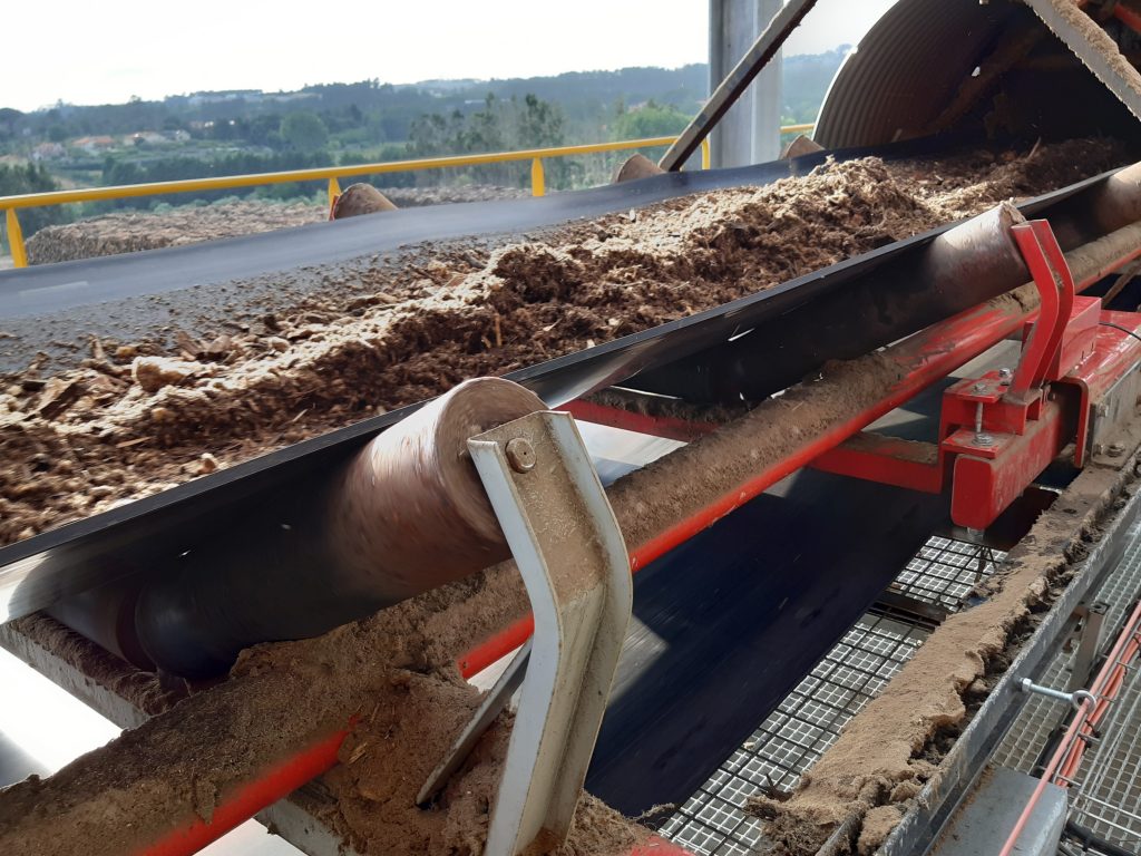
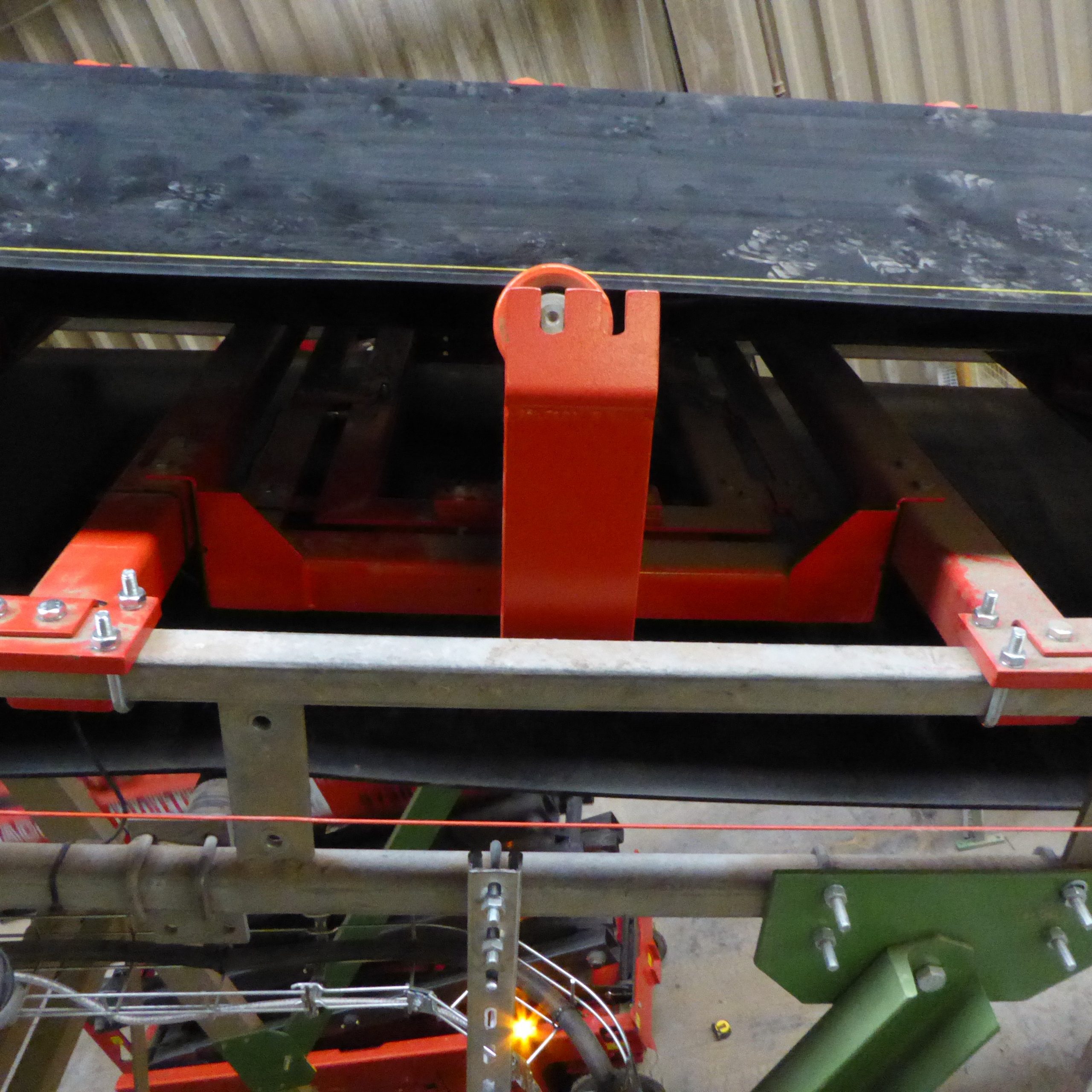
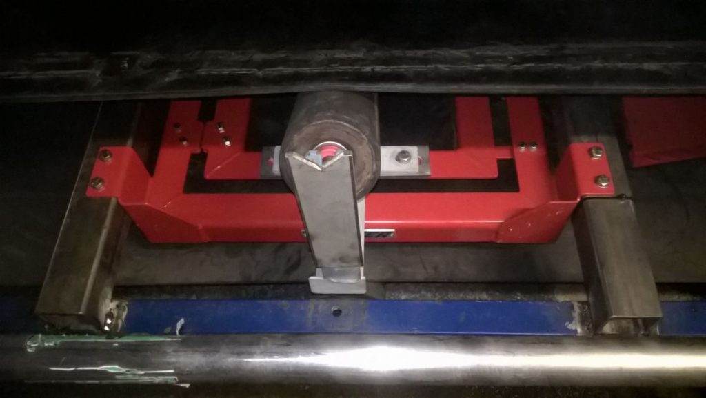
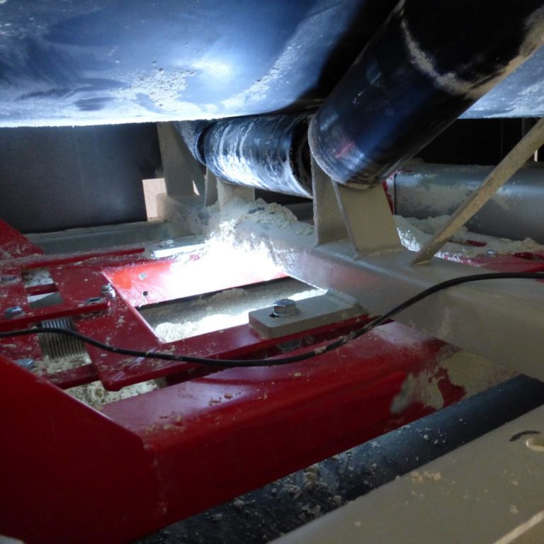
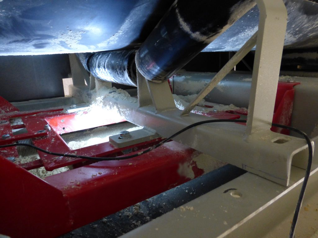
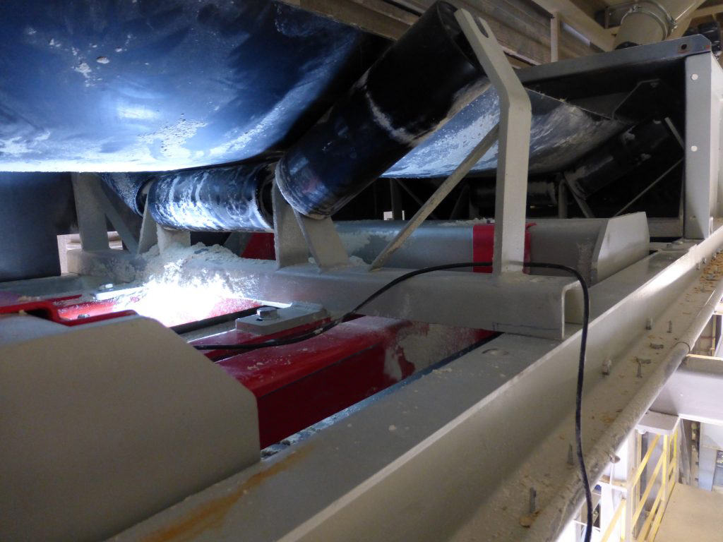
The belt scale consists of a cradle in which the load cell is mounted. The trough is placed in the center of the cradle. The cradle is secured in a frame; on one side using two leaf springs, and on the other side, the cradle is suspended from a load cell. The frame is suspended from two beams laid across the conveyor structure. This allows the entire belt scale to be quickly and easily mounted using 8 bolts on the longitudinal beams of the conveyor structure.
The standard version of the BS 611 is supplied without a trough set. Typically, a trough set from the existing installation is used, which is the most cost-effective and easiest solution.
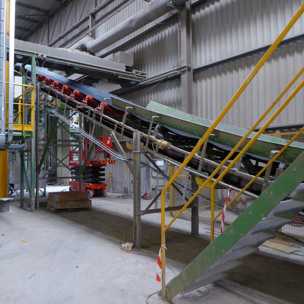
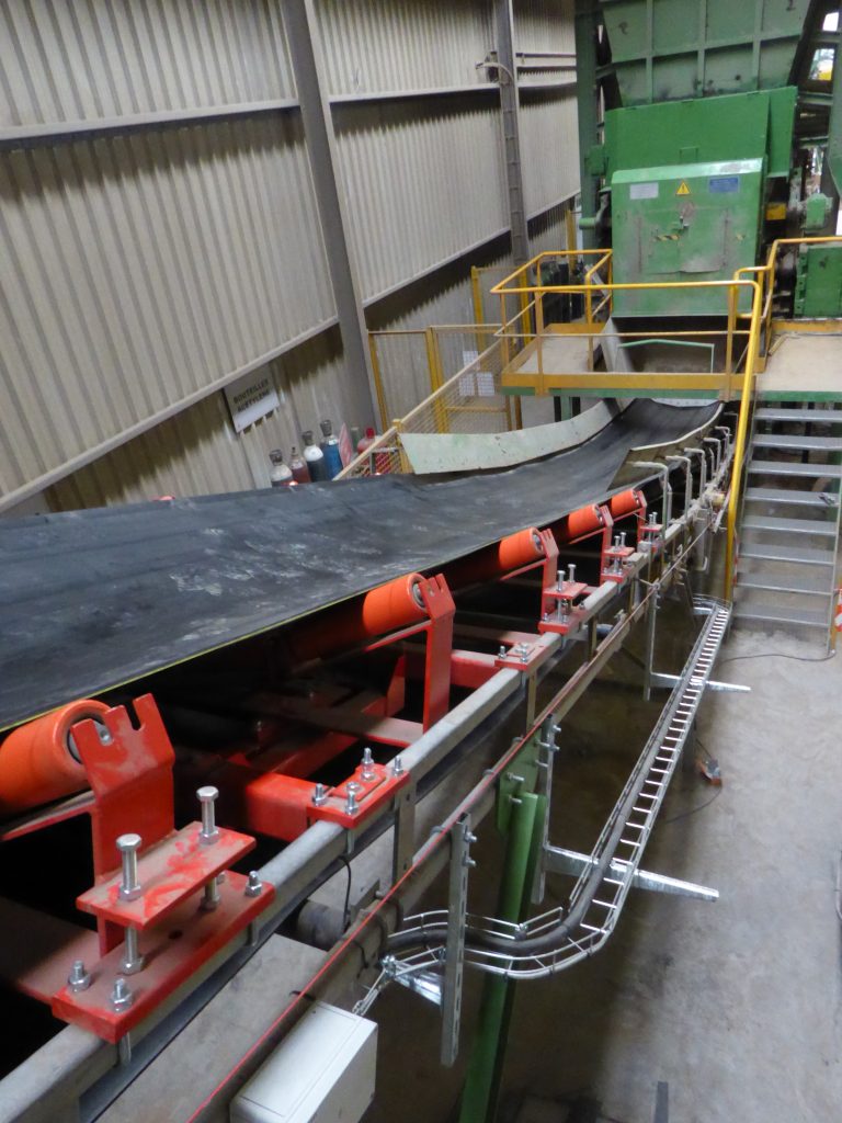
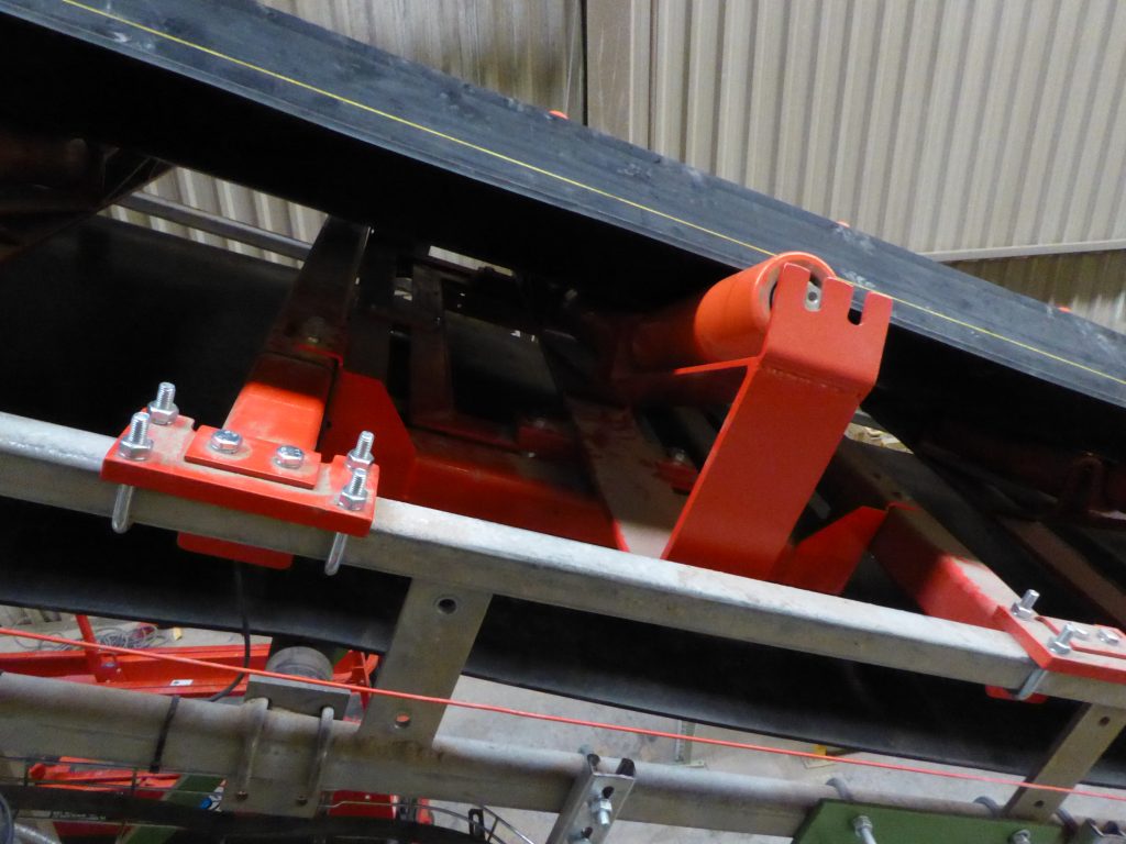
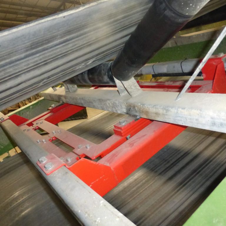
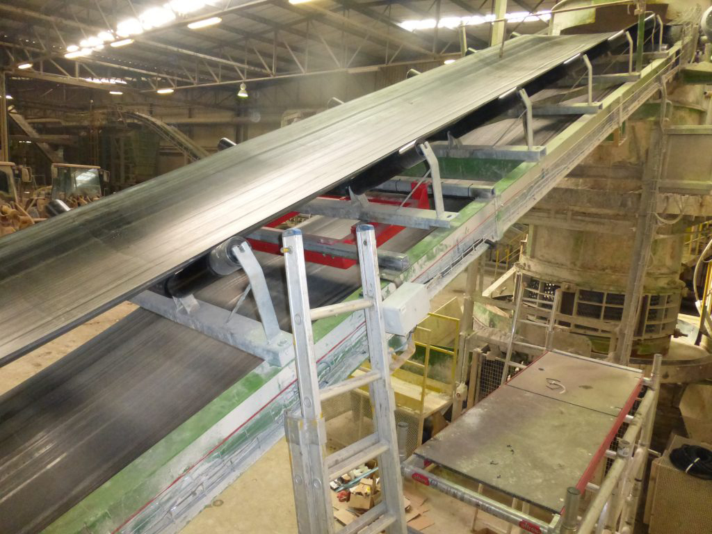
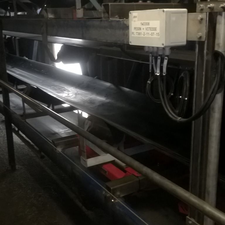
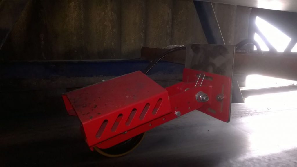
Some of the projects we have completed:




BELT SCALE BS 311 Lowrange
LOW FLOW RATES UNIVERSAL MODEL FOR MULTIPLE BANDWIDTHS FOR FLAT BELTS ONLY

■ 1 set of weighing troughs
■ Coated steel or 304 stainless steel version
■ Suitable only for flat or slightly inclined conveyors
■ Fits into existing installations with minimal modifications
■ INOX IP 67 load cells
■ ATEX version available
■ Accuracy of 1% is possible
■ Flow measurement in aluminum or stainless steel; ATEX-compliant models available
■ Flow rate and volume measurement
■ Weighing amplifier with IP 67 stainless steel housing
■ Outputs: 4–20 mA, Profinet, Profibus, Ethernet, Modbus, and more
■ Suitable only for low loads and low speeds
Design
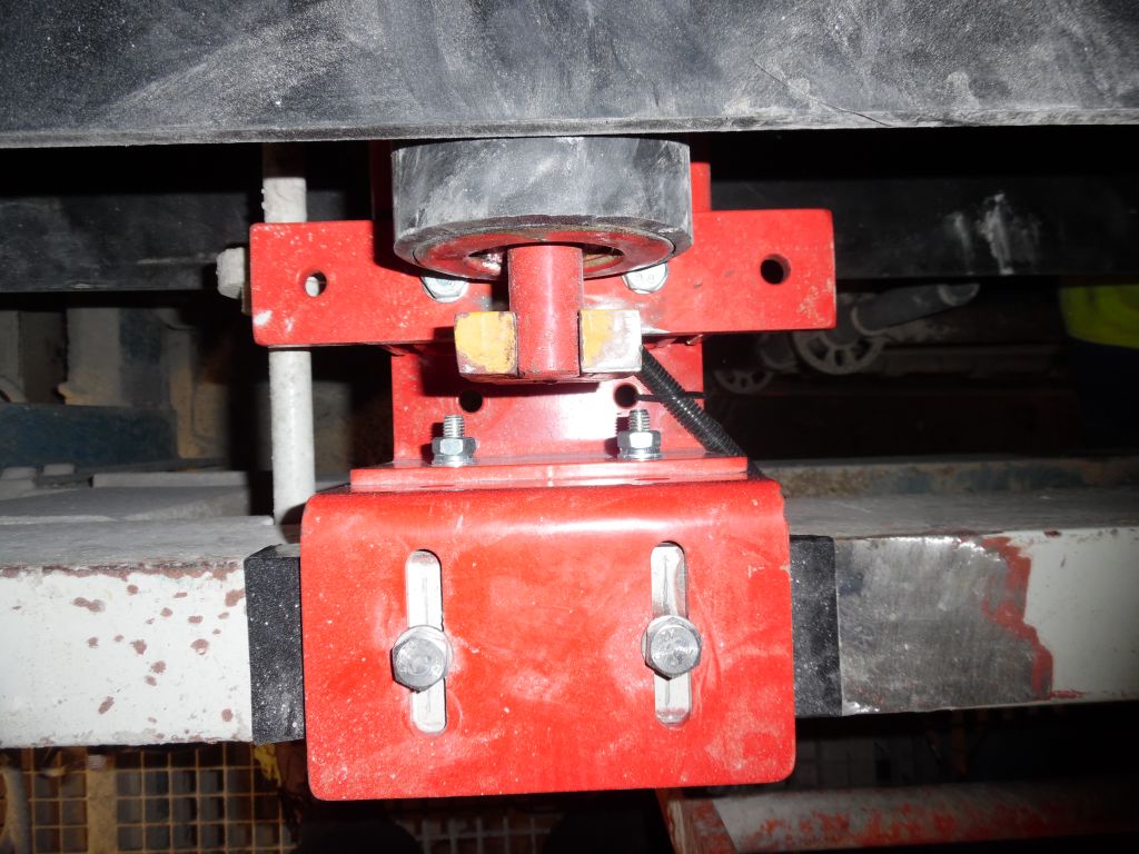
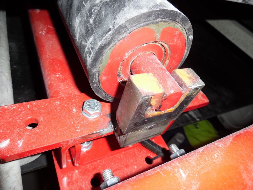
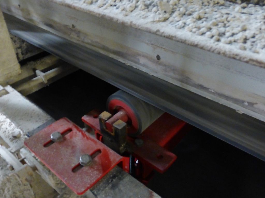
The belt scale consists of a long cradle made up of two profiles with the load cell mounted between them. The trough assembly is placed in the center of the cradle. The cradle is suspended from the longitudinal beams of the belt structure. This allows the entire belt scale to be installed quickly and easily with four bolts.
The standard version of the BS 311 is supplied without a trough assembly. In most cases, the installation’s existing trough assembly is used, which is the most cost-effective and easiest solution.
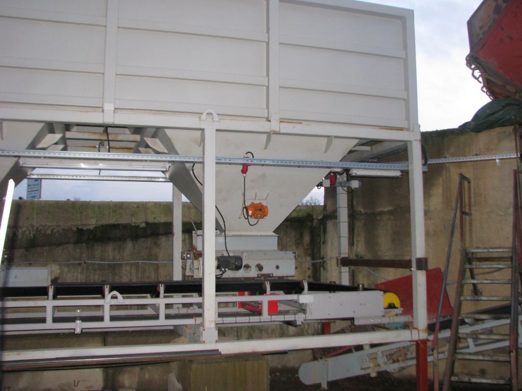
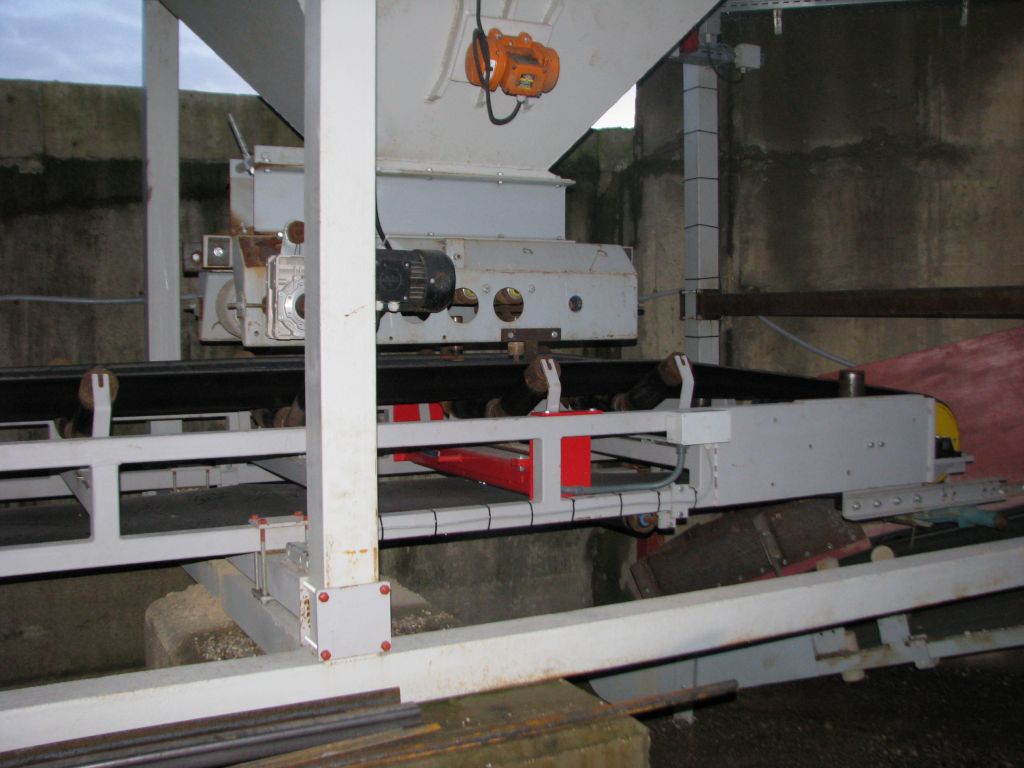
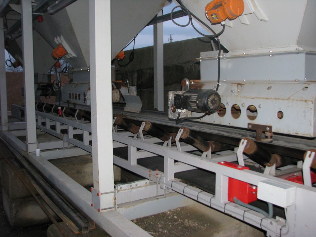
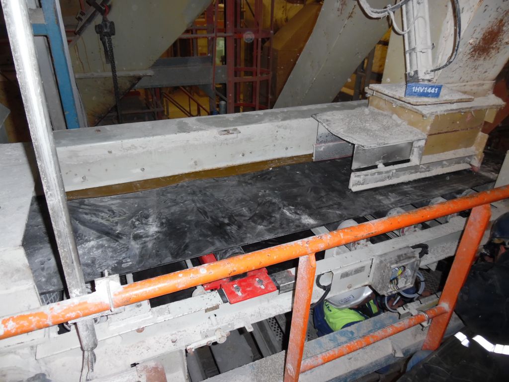
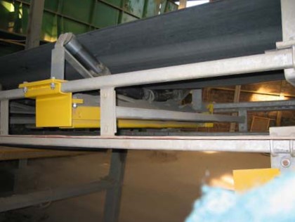
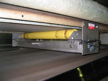
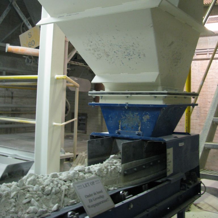
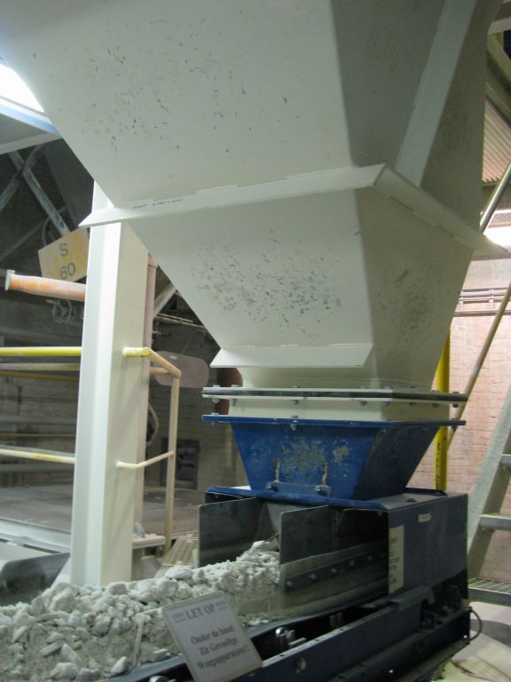
Some of the projects we have completed:





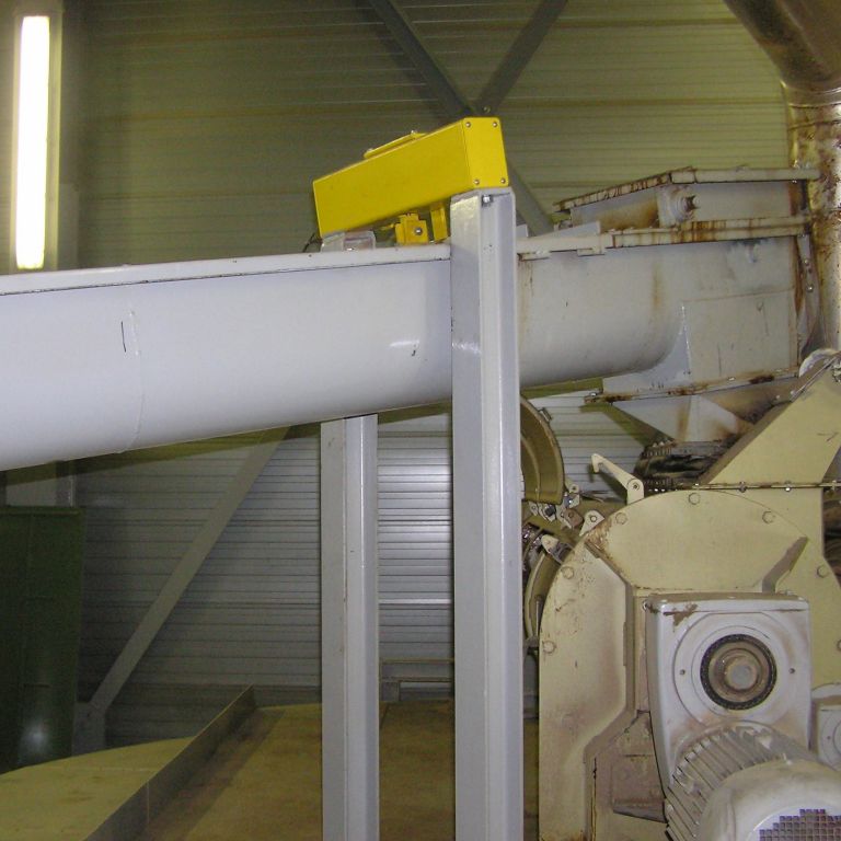
AUGER SCALE
UNIVERSAL SYSTEM FOR ALL SCREW SIZES
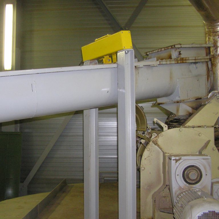
■ Universal model for all screw sizes
■ Steel-coated or 304 stainless steel version
■ Suitable for flat and slanted screws
■ Universal model for multiple belt widths
■ Fits into existing installations
■ INOX IP 67 load cells
■ ATEX version available
■ Accuracy: 1 to 5%, highly dependent on the product and application
■ Flow measurement in aluminium or stainless steel; ATEX-compliant versions available
■ Flow rate and volume measurement
■ Weighing amplifier with IP 67 stainless steel housing
■ Outputs: 4–20 mA, Profinet, Profibus, Ethernet, Modbus, and…
■ Requires flow rates of reasonable duration; not recommended for short start-stop cycles
Design
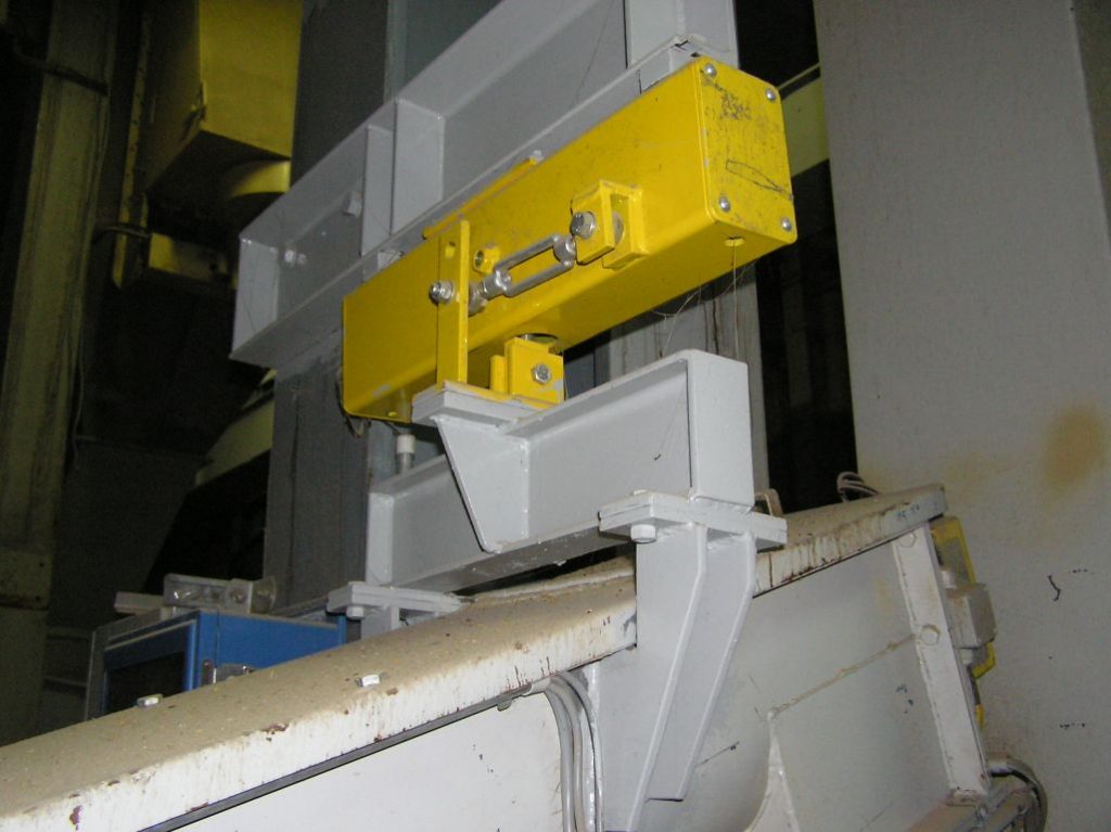
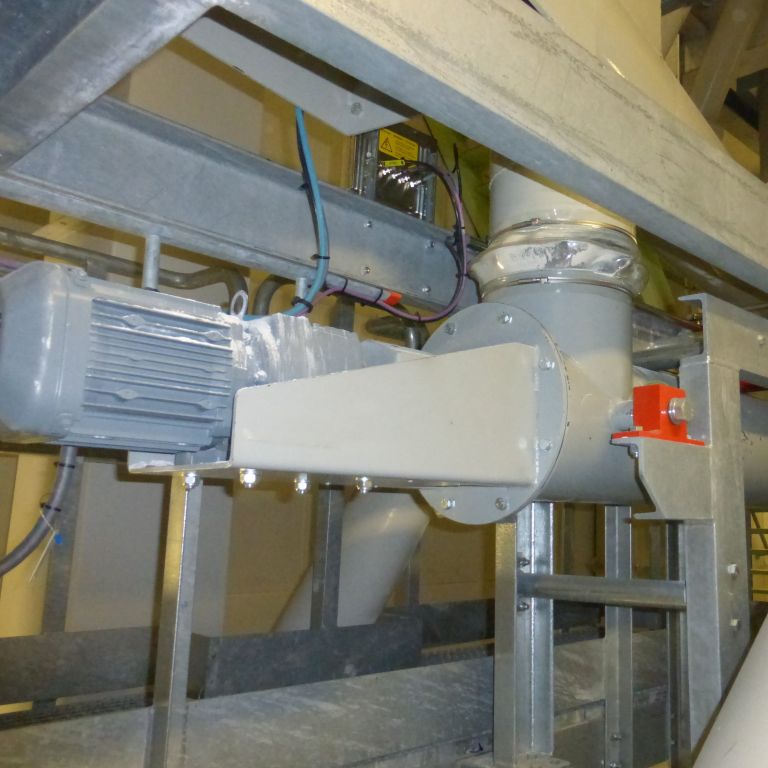
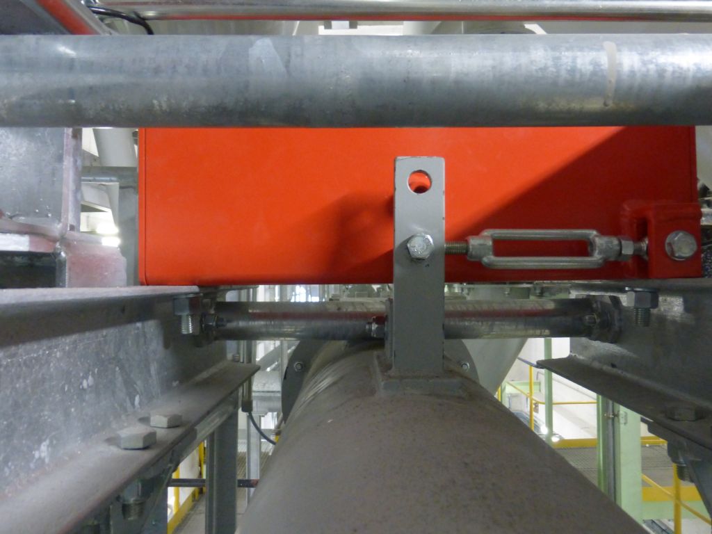
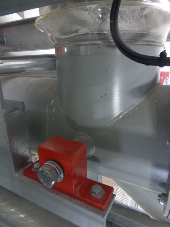
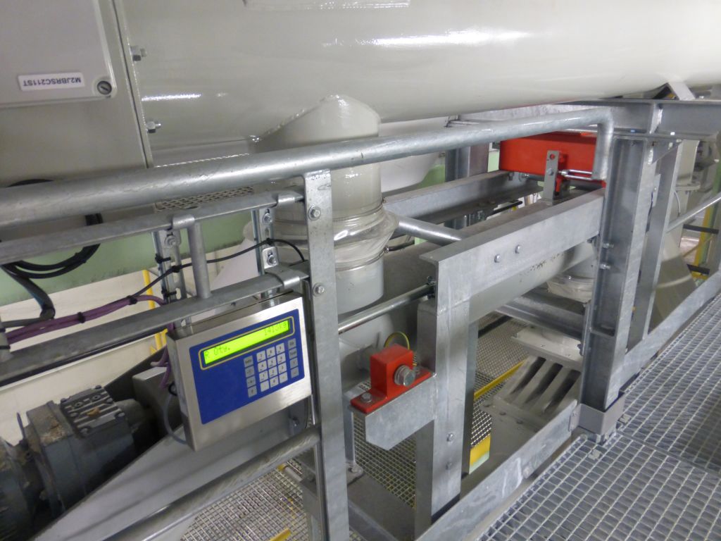
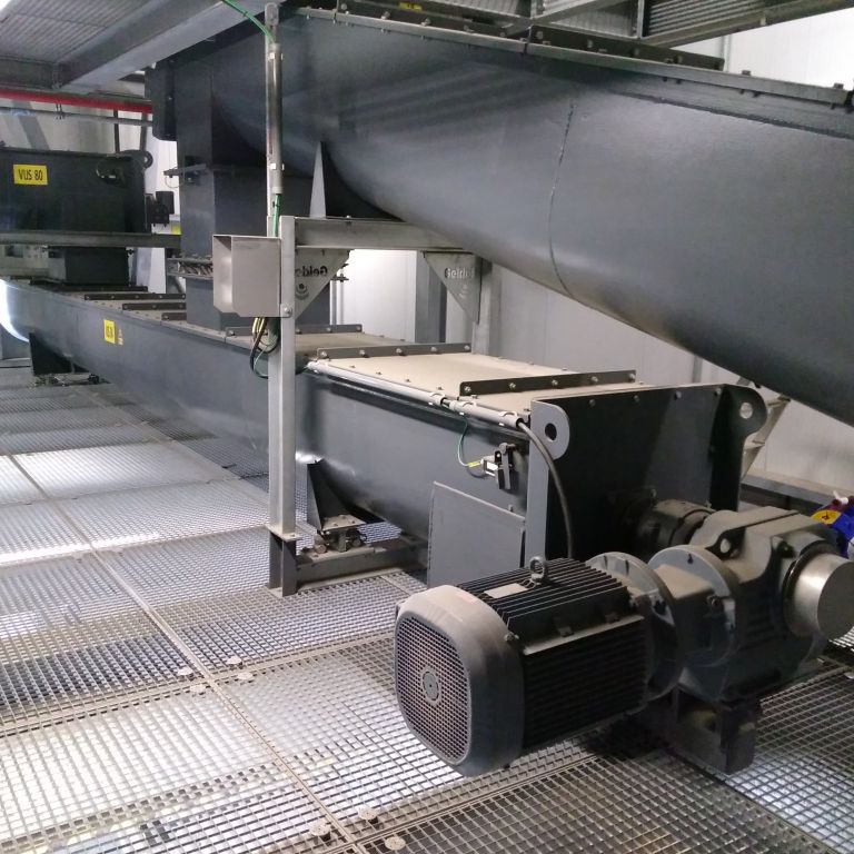
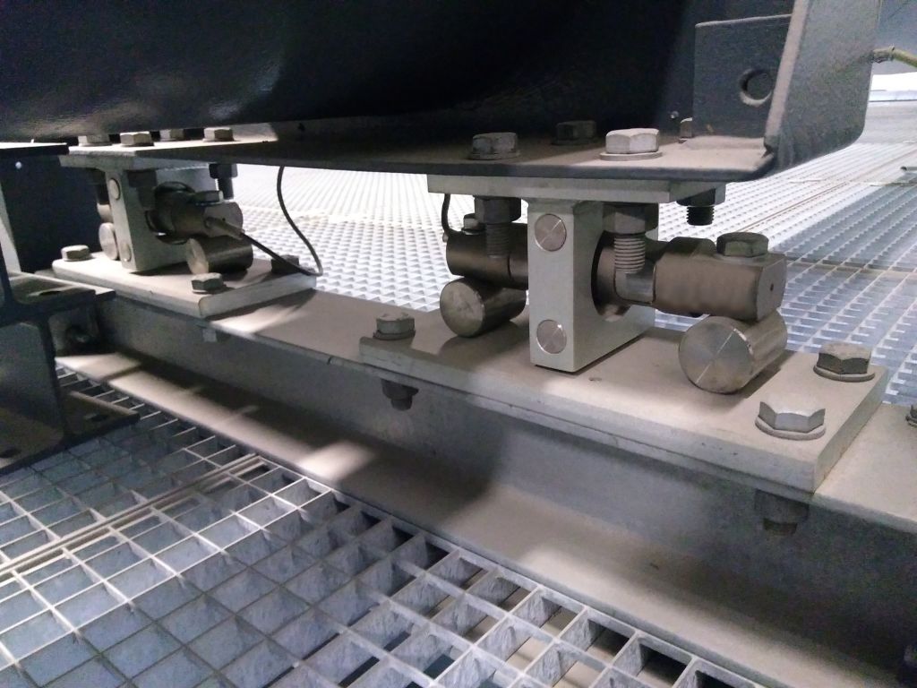
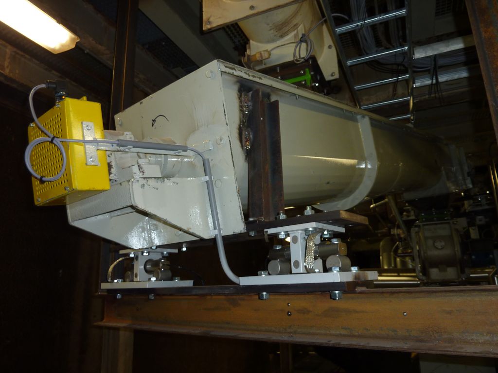
For some applications, the screw is suspended from a weighing system along the discharge side and supported at a pivot point along the feed side. Sometimes, the screw is mounted on two mounts/load cells at the discharge end and supported at two pivot points along the feed side. In certain applications, four mounts/load cells are used.
The screw itself must meet a number of conditions; a “standard conveyor screw” is not automatically suitable for use as a weighing screw. We will explore the options with you, so it is best to contact us early in the project.
Unlike belt weighing, with a screw conveyor it is never certain that the product’s speed matches the (measured) speed of the screw. There may be a difference, and that difference can also vary depending on the characteristics and composition of the product. Screw weighing is therefore used only when no other solution is possible or when the accuracy can tolerate a reasonable margin of error.
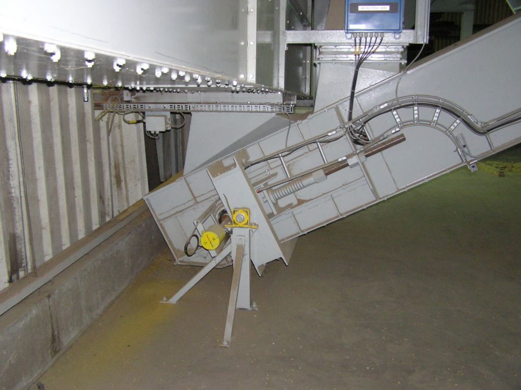
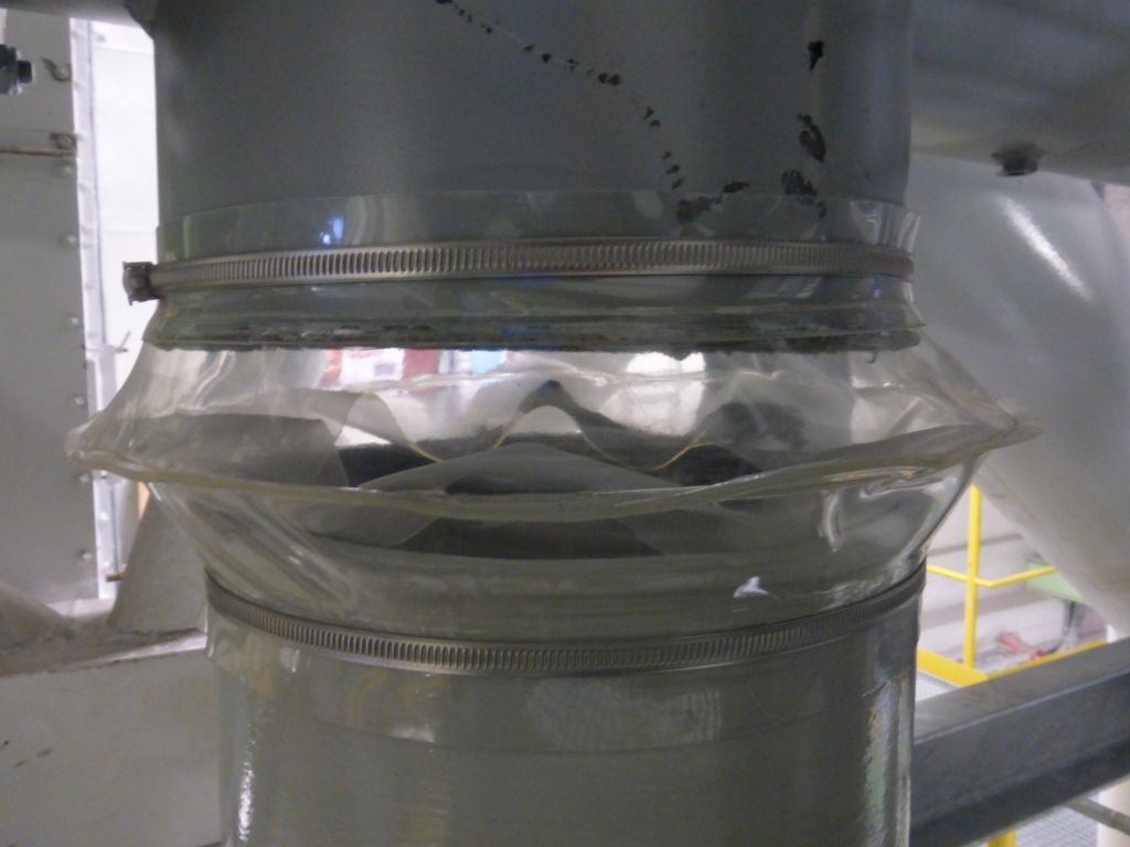
Some of the projects we have completed:




DOSAGE or “LOSS-IN-WEIGHT”
BOTH WITH A “PULL-OUT WEIGHING STRAP” AND A FULLY WEIGHED “DISPENSER”
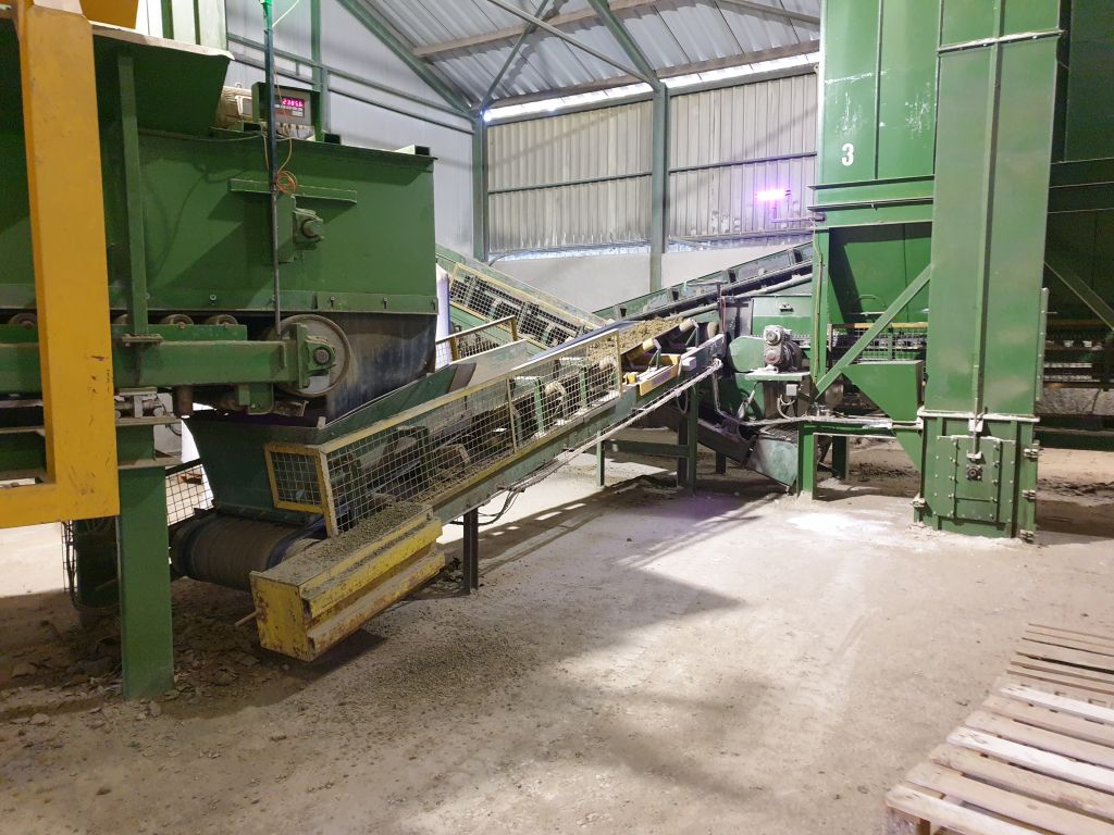
Solution with a pull-out weighing belt:
■ Continuous refilling is possible
■ Relatively lower cost for a large silo or storage bunker
■ Requires longer cycle times per withdrawal
■ Calibration using live weight
Solution with a dispenser:
■ Refilling should ideally be brief, taking no more than 10% of the unloading time
■ Similar costs for smaller bunkers or silos
■ Small batches possible per withdrawal
■ Easy theoretical calibration without live weight
■ Generally more accurate than belt weighing.
What do you mean by a “pull-out weighing belt”?
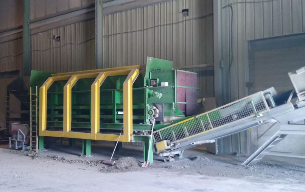
A conveyor belt is placed beneath a silo or storage hopper, with the hopper’s contents resting directly on the belt. As the belt runs, product is drawn out of the hopper. A weighing system is integrated into the belt. This belt must be long enough to avoid being influenced by the product resting on it. To achieve accurate results, the belt must run for some time.
What is a “feeder”?
It is also possible to weigh the entire storage bunker; in that case, it is called a feeder. The accuracy of a fully weighed feeder is surprisingly high. But the bunker must be suitable for this, of course. Fixed connections are out of the question. Another important condition is that the feeder must be refilled very briefly. With continuous refilling, the entire storage hopper cannot be weighed for a “loss-in-weight” application. In that case, it is best to opt for a pull-out weighing belt.
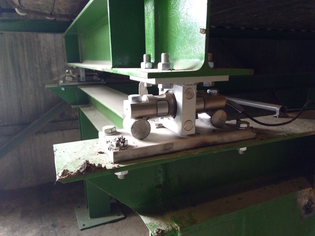
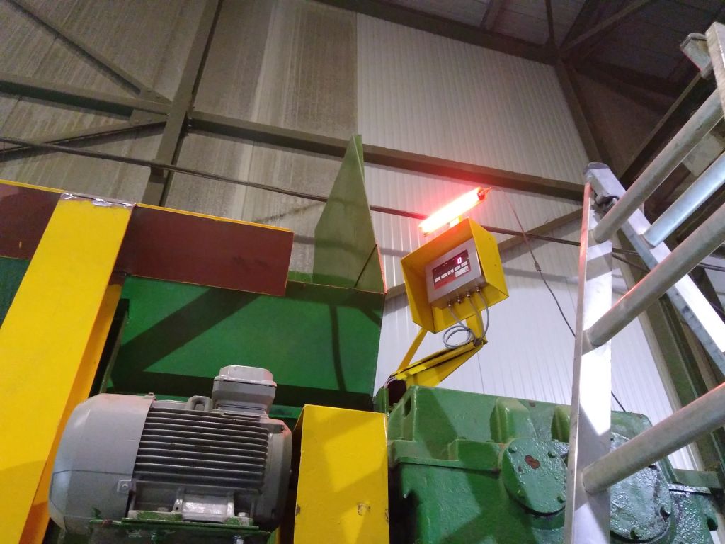
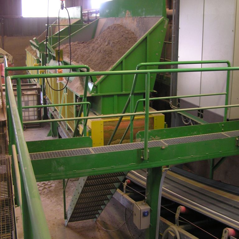
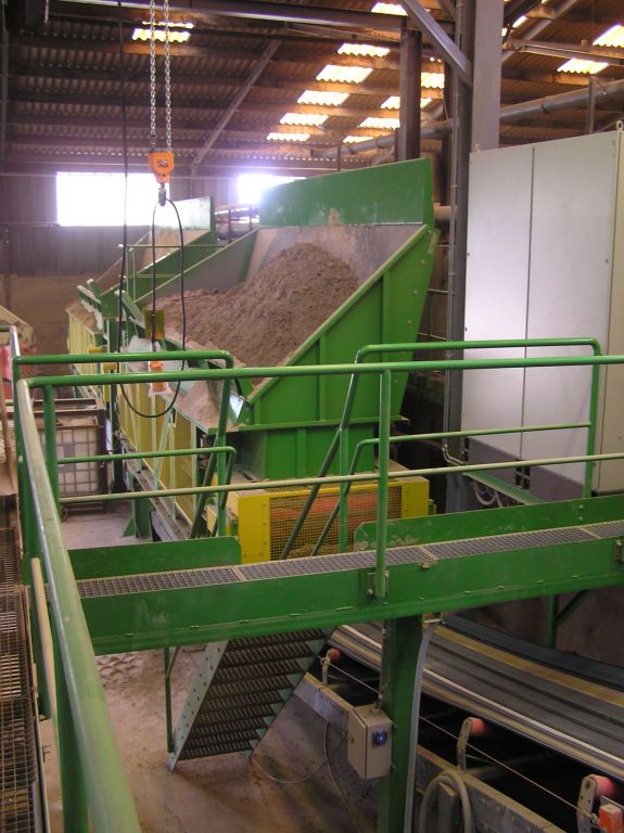
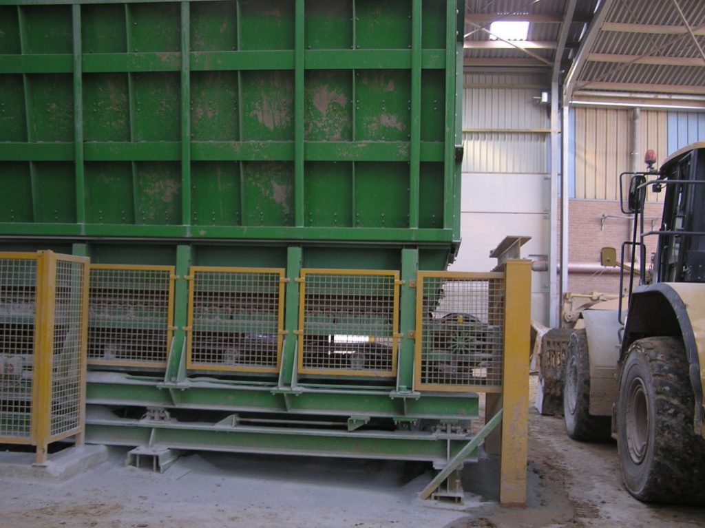
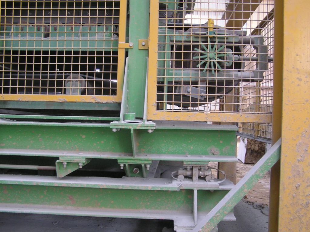
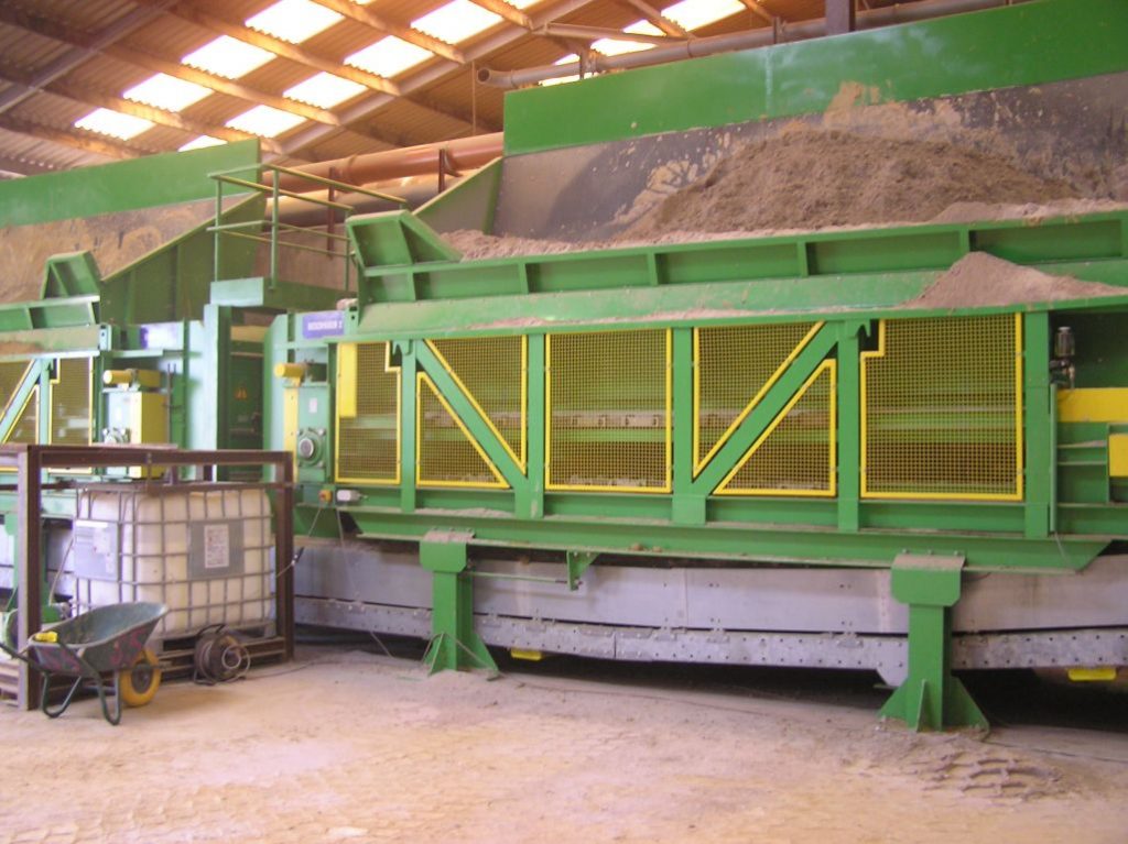
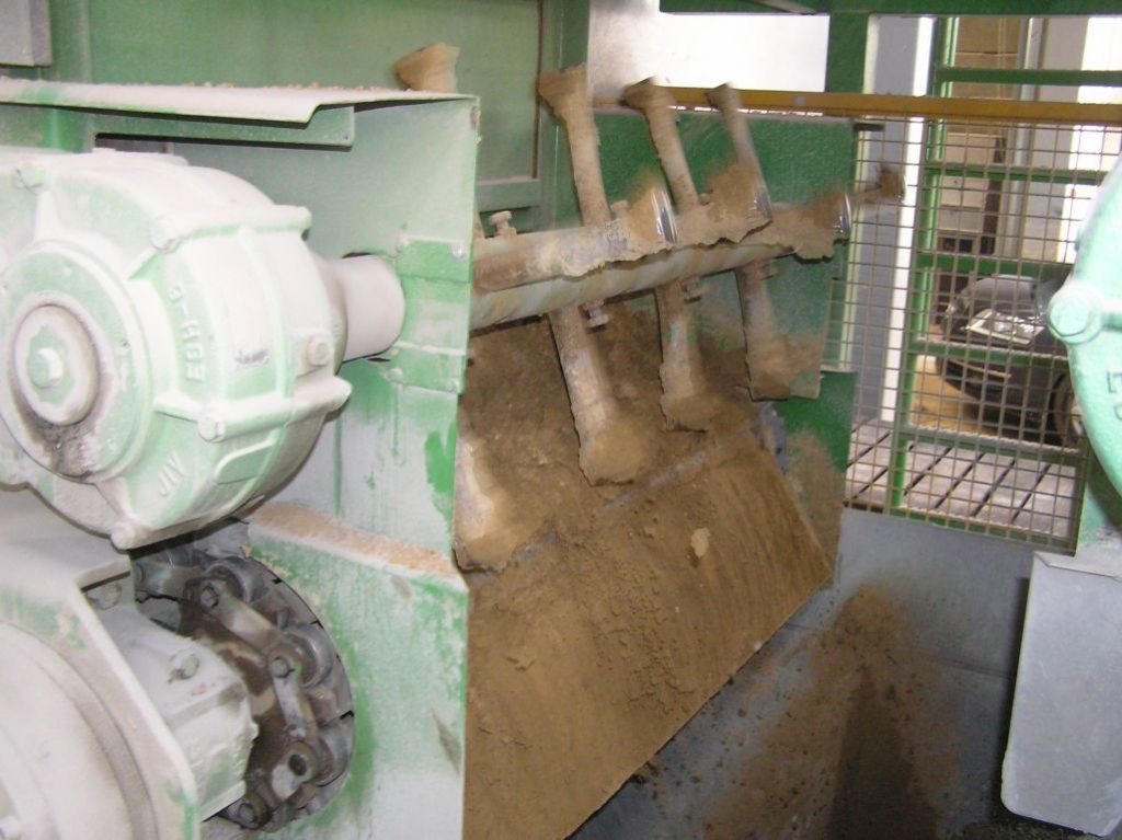
Some of the projects we have completed:




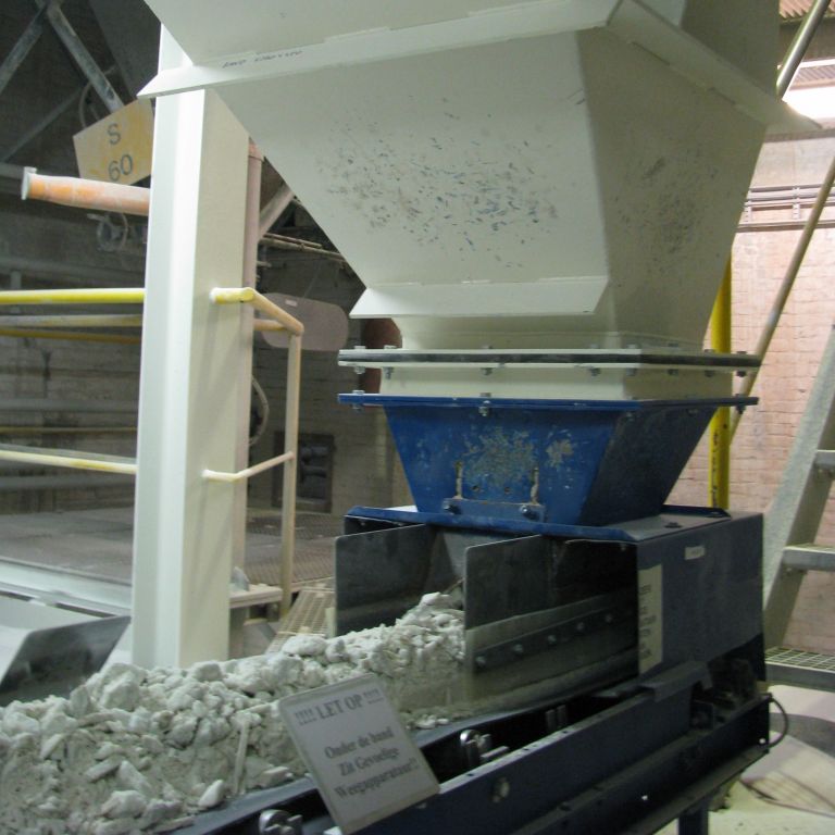


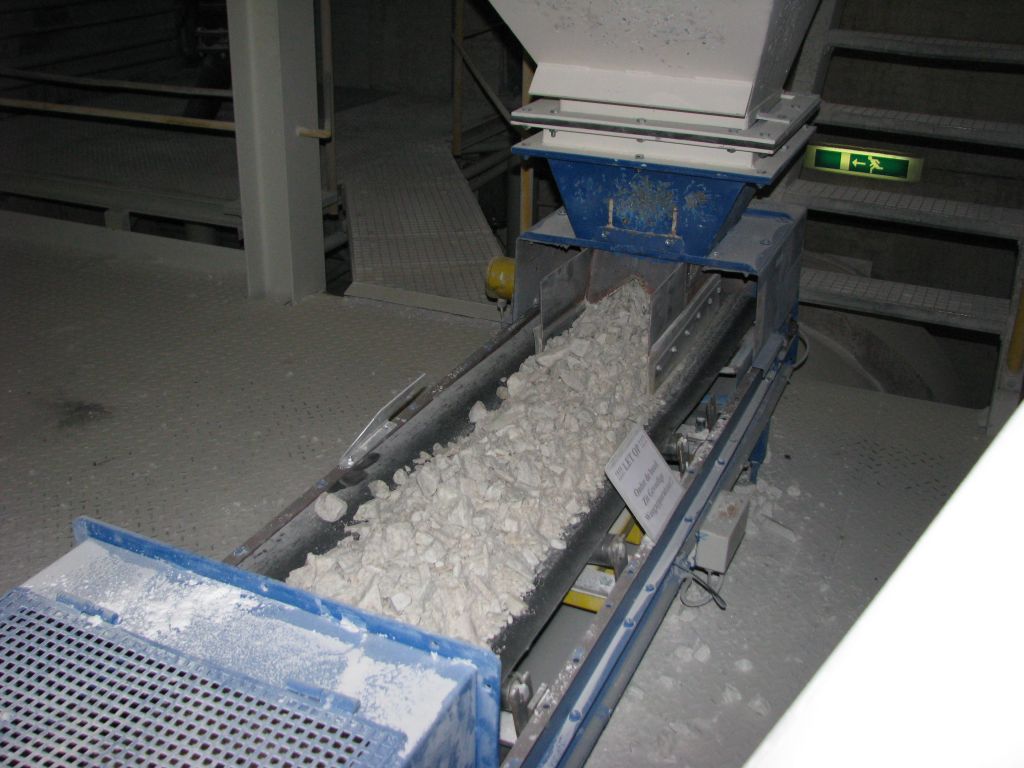
WEIGHING PLATFORM
BULK SLIDE PRINCIPLE
■ For bulk goods
■ No dust formation
■ Easily accessible for maintenance
■ Accuracy depends on the application
■ Available in 304 stainless steel or Hardox
■ Calibration with live weight required (pre-weighing or weighing after passage)
How does a bulk-slide scale work?
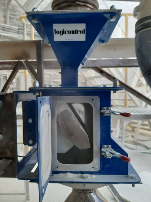
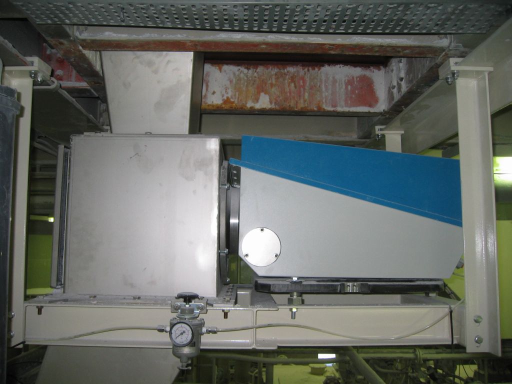
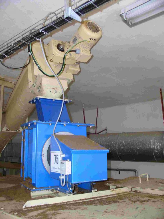
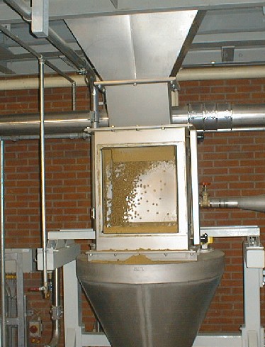
Bulk material is poured onto a plate in free fall. In fact, it is more like a curved chute. The material slides through the chute, as it were, and generates a centrifugal force. This force is measured by a load cell. The higher the flow rate, the greater the force.
However, this measuring principle involves a derived force and is therefore not directly proportional to the weight, but rather to an “effect” caused by the product. For this reason, calibration with “live” product is necessary. Significant differences in composition, density, and moisture content can reduce accuracy. This is therefore a rather rudimentary measurement, not comparable to a “true” weighing system.
It is therefore best to consult with us regarding the feasibility of an application.
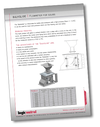
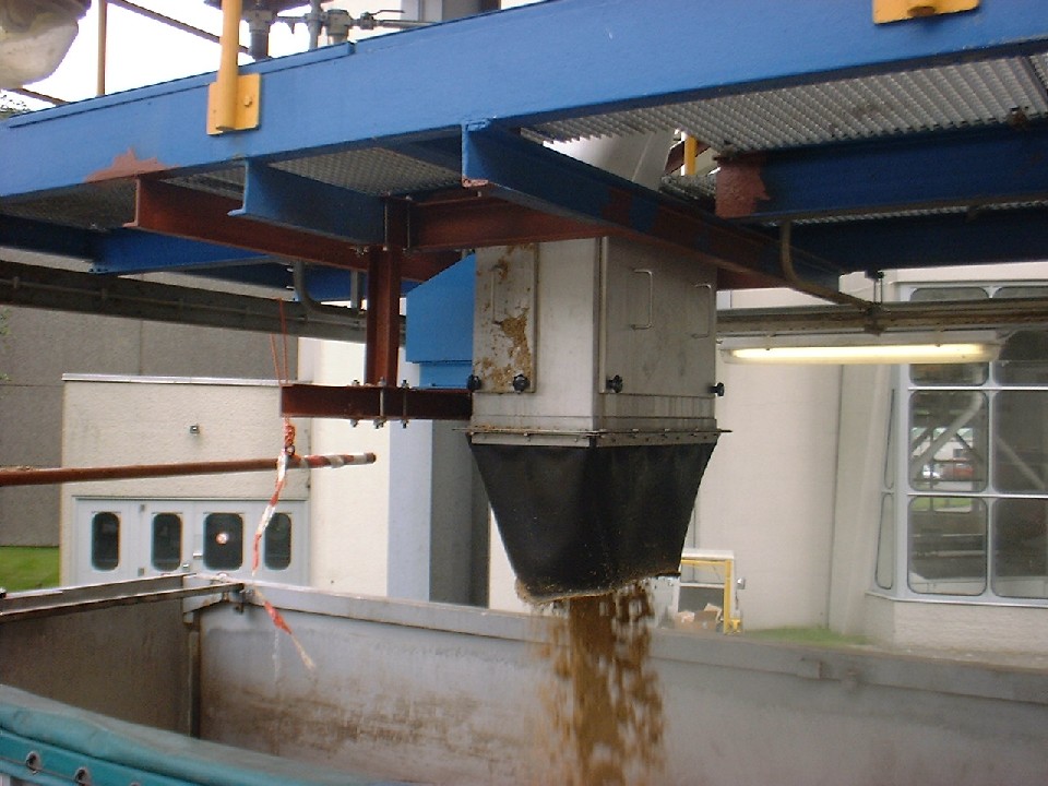
Some of the projects we have completed:
Logicontrol
Vrijheidslaan, 177 1080 BRUSSELSTel: +32 2 414 62 36
logicontrol@logicontrol.be