Nederlands
 Français
Logicontrol
Vrijheidslaan, 177 1080 BRUSSELSTel: +32 2 414 62 36
logicontrol@logicontrol.be

The main purpose of this page is to draw your attention to potential sources of problems in your project.
Are you familiar with what we’re describing and do you know what to do? Great. If what we’re describing sounds unfamiliar to you, it’s best to consult with us. It’s not always possible to provide a solution right away for every topic covered. Many solutions vary from project to project, so it’s best to discuss these matters in consultation. There’s also a risk that things might be misinterpreted. It’s important to realize that installing a 200-metric-ton silo is quite different from installing a small 450-kilogram hopper, especially when it comes to safety.
If you have a project, please contact us, and we’ll work with you to determine the best approach.
The total weight of the silo, filters, motors, valves, mixers, and, of course, the contents, divided by the number of load cells. If there are 3 load cells, you divide the weight by 3. It’s always wise to maintain a small margin. If the silo is mounted on 4 load cells, it’s advisable to allow for 30% overcapacity, as it’s quite possible that at certain times the silo won’t rest on all 4 load cells, which could result in one load cell having to handle a significant additional load. We’ll go into more detail on this in “Weighing Systems with More Than 3 Points.” Placing a 200-metric-ton silo on four 50-metric-ton load cells is not a good idea—this will definitely go wrong.
If your silo is located outdoors, you must take into account that strong winds will add an additional wind load to the silo’s weight.
Load cells are more accurate than you might think (accuracy). It is therefore safer to use a higher capacity, especially if this does not result in a price increase. Why and when you should opt for higher measurement ranges will become clear as you continue reading this questionnaire.
There are quite a few misconceptions regarding the accuracy of load cells.
The most common calibratable load cells have a C3 class, which means 3,000 divisions. (In weighing applications, the term “divisions” is used rather than percentages or absolute weights. A calibratable scale is used for selling goods by weight and is subject to strict official controls.)
Many users in the process industry assume that a load cell with 3,000 divisions is no more accurate than the load cell’s capacity divided by 3,000. So, a 3,000 kg load cell could not weigh anything more accurately than 1 kg. This is a serious misunderstanding!
This “C3” (3,000 divisions) actually refers not to the load cell itself but to the scale in which the load cell will be used.
The C3 marking on the load cell specifies that, in accordance with calibration regulations, you may use this load cell to build a calibratable scale with a maximum of 3,000 divisions. So, for example, the scale has a capacity of 3,000 kg, weighed in 1-kg increments. You can build this scale using 4 load cells rated at 1,000 kg each. But you can also build this scale with, for example, 4 C3 load cells rated at 2,000 kg each! While you’ll have a total weighing capacity of 8,000 kg, you can still weigh in 1-kg increments. The load cells are therefore much more accurate than their weighing capacity divided by 3,000.
How accurately—or how “small” a weight—you can measure with a particular type of load cell is not determined by the C3 designation but by the “minimum verification interval,” which roughly translates to the smallest calibrated increment.
To summarize again: load cells are much more accurate than their weighing capacity divided by 3,000.
The “smallest verifiable division” tells you the true accuracy of a load cell. Unlike the C3 designation, the smallest verifiable division does provide important information about the load cell. This information can be found on the load cell’s datasheet under the legally required designation “minimum verification interval.” On this website, we have referred to this as the “Smallest legal approved division” for convenience.
For the load cell, this determines the smallest value that may be displayed on the screen of a legal-for-trade weighing instrument. For the SHBxR load cell, this is the load cell capacity divided by 15,000. For a 30-kilogram SHB load cell, this is therefore 2 grams.
But in reality, the load cell is even more accurate than this smallest legal unit…
Indeed, a “calibrated” scale must be more accurate than what it indicates.
Suppose you’re selling 1,200 kg of fruit and weighing it by the kilogram on a scale with a capacity of 10,000 kg and a smallest calibrated division of 1 kg. If the total weight is, for example, 1,200.3 kg, the scale must display 1,200 kg. However, if the total weight is 1,200.7 kg, the scale must display 1,201 kg. To make matters a bit more confusing, a legally calibrated scale must be accurate to within ½ scale division for the first 500 divisions out of the 3,000 divisions it is authorized to weigh.
In other words, the load cells must be even more accurate than the smallest calibration-grade division that the load cell is permitted to weigh under calibration regulations.
When multiple load cells are used in a scale, additional rules apply under calibration regulations, but we’ll set that aside for now.
Specifically: the smallest calibrated unit gives you an idea of the maximum accuracy you can expect from your weighing system.
For example, if you want to weigh a 250 kg hopper with, say, an accuracy of 0.1% (i.e., 250 g), it’s best to use three 200 kg SHB load cells. The smallest division of an SHB load cell = 1/15,000th of 600 (= 40 g). More than enough! So you can easily weigh a 250 kg hopper with a 600 kg weighing capacity. Easy!
Many terms used in load cell data sheets—such as “C3,” “divisions,” “minimum verification interval,” etc.—relate to calibration regulations. All sales of goods by weight—for example, using a retail scale in a supermarket or a truck scale—are governed by calibration regulations. This European legislation for weighing instruments is quite complex, and applying it is a profession in its own right.
This legislation does not apply to process weighing. What exactly do these specifications tell us about the load cell itself? And, more importantly, how should one interpret this in a process environment? Take, for example, the “minimum verification interval.” This can easily lead to misunderstandings if you are not familiar with the meaning of the terminology used. Explaining all the terminology used in data sheets here would take us too far off topic. If you would like to know what to expect from a load cell, please contact us; we will be happy to discuss this with you.
Tall silos catch a lot of wind. This wind force is added to the total weight and, of course, is transferred to the load cells. First and foremost, it is important that the load cells can withstand this increase in weight; otherwise, they will be damaged. It is also important to install tilt and uplift protection. After all, load cells simply cannot guarantee the safety of a large silo.
The commonly heard argument—“But aren’t load cells made for this?”—is a misunderstanding. After all, load cells are designed for weighing, and they are subject to wear and tear over time. It is therefore not impossible for a load cell to fail at some point. (e.g., after 10 years and during an exceptionally severe storm). In such situations, the mounting hardware surrounding the load cell must ensure that the silo remains upright. It must also ensure that the silo cannot be lifted, even after a load cell has failed.
Calculation Method:
There are various methods for calculating “uplift” and wind load, which are specified in a wide range of national and international standards. Strangely enough, some standards use different calculation methods for the same wind force. It is therefore important to determine which regulations apply to your silo project, as these can vary, especially outside the European Union.
For tall silos, it is best to leave the calculation of these forces to the silo manufacturer or a specialized engineering firm. We do, however, offer a few important tips:
You need to know where your silo will be located; wind standards in Scotland, Wallonia, or Florida differ. The surroundings are also important: if the silo is located by the sea on top of a dike, or something similar, this situation will amplify the normal wind. Is there a possibility that structures will be placed on top of the silo—now or in the future? These are all questions you need to ask yourself, and they will help determine the choice of load cells or the required capacity.
However, be critical and cautious. Here’s an example: Some methods for calculating wind load specify that when multiple silos are arranged in a row, the calculated wind load must be increased by a factor of 0.2. This makes sense because the silos form a “barrier” and thus catch more wind. Strangely enough, there are calculation methods that make no mention of this… Be careful!
In weighing projects, the importance of mounts is often underestimated.
To those unfamiliar with them, they may seem like an extra cost; in reality, however, they actually make the entire project more cost-effective, safer, and more accurate. And when installed correctly, they ensure that the system maintains its accuracy for many years without any hassle.
Safer? Indeed, weighing a silo or tank mounted directly on the load cells without mounting brackets is a dangerous situation. The often-heard argument—“What do you mean? Aren’t load cells made for that?”—is a misunderstanding. After all, load cells are designed for weighing, and they “bend” and degrade over time. Therefore, load cells alone cannot guarantee the safety of your silo. If a load cell were to fail, there must be something to prevent the silo from collapsing. In most cases, this can be resolved with a mounting bracket.
Cheaper? Absolutely. The cost of a weighing system isn’t determined solely by the cost of the components. The cost (and time) of installation, alignment (which is so often underestimated), and calibration are also part of the total cost of a weighing system. The cost of troubleshooting problems after the fact—if something turns out not to be working properly—can be high, especially if production has already started, the installation is located overseas, etc. Our mounts are designed to significantly reduce all these costs and ensure that everything is installed properly the first time. Our mounts come with very clear installation instructions.
To keep this already lengthy text from becoming overwhelmingly long, we won’t discuss on this page “how” mounts make a project more accurate, cheaper, and simpler. After all, the approach differs for each mount.
If you haven’t yet chosen your equipment, you might be tempted to read through everything, which only makes things more confusing. Once we’ve determined, in consultation with you, which equipment is suitable for your project, you’ll receive a document explaining how the selected mounts provide these benefits. If you’re not yet familiar with how our mounts work, please don’t hesitate to contact us.
Load cells must be able to bend in order to measure. Simply put, load cells are metal components that can be mounted on a structure. These components are “weakened” at critical points so that they will bend when a weight is applied. Thus, at the slightest increase in weight, the load cell must bend a little further. Typically, this bending over the entire measurement range is only 0.2 mm, and in exceptional cases (small measurement ranges), it can reach up to 0.5 mm. It is clear that a load cell that bends at the slightest increase in weight could fail completely if overloaded. A load cell is therefore not a safety device.
A load cell works as follows: the bending is measured using resistors called “strain gauges,” which are bonded to weakened areas in the load cell body. Inside the load cell is a small electrical circuit that ensures the signal varies linearly with the increase in weight and that this output matches that of the other load cells in the same system. The electrical circuit is sealed against moisture and dust.
This sealing (of the weakened areas) actually prevents the user from seeing just how “thin” the load cell really is in those spots.
You can safely assume: if you were to see a “stripped-down” 2-metric-ton load cell with 2 metric tons of weight on top of it… you’d never dare stand underneath it!
The statement “What do you mean? Aren’t load cells made for that?” is a misconception. Load cells are not safety devices. Load cells are designed to weigh, which is why they must be able to bend; this implies that load cells do indeed pose a risk in a silo project. Protection against wind or overloading must not be left to the load cell itself but must be provided by the mounting hardware or safety devices specifically designed for this purpose.
Silos, hoppers, and mixers that rest solely on load cells without any hardware protection against load cell failure or tipping pose a significant safety risk.
Anything attached to the silo that forms a rigid connection with its surroundings affects the weighing process, as these connections bend under the influence of weight changes. Although this bending is very small (typically 0.2 mm over the entire measurement range), it is nonetheless essential. You should view a silo being weighed as an object that must be able to move freely up and down, and nothing should hinder this movement. Ideally, of course, you should design your project so that there are no fixed connections whatsoever between the silo and anything surrounding it. It is always possible to decouple ladders and walkways from the surrounding structure. Be sure to avoid any fixed horizontal connection between two silos. After all, if one silo “sags” under load, it could pull on the other silo; due to a lever effect, this can generate considerable forces leading to surprisingly large weight deviations.
Essential connections should ideally be made flexible, using fabric, plastic, or flexible materials.
A fixed connection—for example, a vertical pipe rigidly attached to the support structure beneath the silo—acts as a fifth support point in addition to the four load cells. The consequences of this can drive you completely crazy. Suppose you’re checking the weight by placing extra weight on the load cells. Depending on where you place the load (on which load cell), different leverage effects come into play. Sometimes the weight is much too light; on another leg, it’s much too heavy. Someone unfamiliar with this subject will have a hard time identifying the cause of these strange phenomena, especially if there are multiple connections on the silo or tank.
It is a fact that a silo with fixed connections can never weigh as accurately as a silo that stands completely free. However, it is indeed possible to attach piping without flexible connectors to a tank while still minimizing the impact to a manageable level.
This is described in a brochure available from Logicontrol upon request. To avoid misunderstandings and undesirable situations, we do not publish this information on this site. After consulting with you and reviewing your situation, we will indicate which techniques described in the brochure can be applied and what results you can expect.
This topic is a great opportunity to show that it’s not always that simple. Both options have pros and cons; some aspects are underestimated, and the right choice depends on your priorities and the specific application. Here’s the explanation—it’s a bit long, but it covers every aspect.
Price:
Of course, 3 load cells are cheaper than 4 load cells.
Three or four load cells in terms of accuracy.
As long as a load cell isn’t overloaded, an uneven load distribution doesn’t matter. During calibration, a weighbridge is always loaded at the 4 corners with 1/3 of the weight on ¼ of the surface area. And this is done for all 4 corners. In this way, one load cell bears almost the entire load each time, while the other 3 bear almost nothing. The results for the four corners must be equal AND fall within the weighbridge’s accuracy tolerance; otherwise, the weighbridge is rejected. This is the best proof that uneven loading does not affect accuracy. A weighbridge or a scale… They all rest on four points.
Three or four load cells regarding load cell capacity.
A silo supported by three load cells distributes its weight—especially when completely full—evenly, with one-third on each load cell. A silo supported by three load cells will also never wobble. A silo supported by four load cells never distributes its weight equally—one-fourth on each load cell. A silo supported by 4 load cells can wobble if the load cells are not at the same height, causing the weight to be briefly concentrated on just 2 load cells! This can be dangerous.
Consequences: A 30-metric-ton silo can safely be placed on three 10-metric-ton load cells. A 40-metric-ton silo should never be placed on four 10-metric-ton load cells; you must always provide “reserve” weighing capacity. Even a 30-metric-ton silo should not be placed on four 10-metric-ton load cells; it’s best to opt for four 15-metric-ton load cells. If the 15-metric-ton load cells aren’t more expensive than the 10-metric-ton ones, don’t hesitate to use the 15-metric-ton load cells.
Three or four load cells, depending on the supporting structure.
Are the load cells mounted on sufficiently sturdy concrete? If so, it makes little difference whether we use 4 or 3 supports.
If the load cells are mounted on a steel substructure… then it’s a whole different story. Mounting at three points means placing a load cell somewhere in the middle of a beam. That beam is guaranteed to bend (yes, it will), and that can have consequences. If the silo is secured to its surroundings with piping, etc., the bending of a beam will cause the silo to pull or “hang” from a fixed point, resulting in errors. This works like a lever; do not underestimate these forces—they can easily reach several hundred kilograms or more.
It’s even worse when two silos share a single load cell on the same beam. When Silo 1 is filled, it causes the beam to bend, which in turn causes Silo 2—which shares that same load cell on the beam—to pull and sag at a fixed point. The result: Silo 1 is filled, and Silo 2’s weight changes by a few hundred kilograms. Some customers can get quite upset about this. And of course: the load cell supplier comes under scrutiny and gets the blame because the weighing system is “measuring incorrectly.” “And they all have it, sir. You have to fix this! ” But the root cause lies in the choice of three load cells, the steel structure being too light, and the way it’s secured to the surrounding structure… that is unsolvable. If the purpose of the weighing is dosing, this issue can completely throw off the entire dosing process. In this case, opting for three load cells was a poor choice with significant consequences.
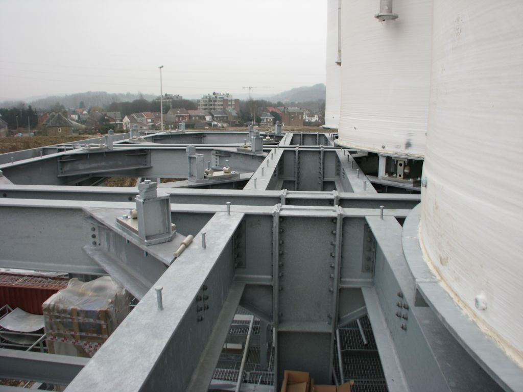
Take a look at the third photo in the column on the right. The application: precise dosing from a 200-metric-ton silo into a truck. The load cells are mounted on four diagonal beams at the corners of a square. These beams are exceptionally rigid and are also positioned right next to a support leg. That diagonal beam will not bend. So the silo rests on four very rigid support points.
Furthermore, a separate beam has been provided for each silo here. So there is absolutely no “interaction” between the silos themselves. A large-diameter silo always “settles” slightly, and this compensates for the small differences in support height. The silo is well supported, distributes its forces effectively, and has no interaction with the other silos = excellent and safe weighing.
Three or four load cells for safety in extreme wind conditions.
A silo supported by 3 load cells has only one support point to resist the wind. A silo supported at 4 points has two points to resist the wind. This is a factor that should not be underestimated!
Conclusion.
Whether it’s better to use 3 or 4 load cells will depend in part on the structure the silo is mounted on: a concrete slab, a concrete floor, or a steel structure.
It also depends on the silo’s tonnage. A small 10-metric-ton silo on a thick concrete slab (even on a concrete floor) = no problem with 3 load cells. A 400-metric-ton silo on a steel frame (e.g., shown here) = 4 load cells.
If the silo is indoors = no wind = it’s easier to opt for 3 load cells. If the silo is outdoors = you should consider whether 4 wouldn’t be safer.
If several silos are grouped together in a tall steel structure AND high accuracy is required = you’ll need 4 load cells.
If the silos aren’t too heavy—50 to 80 metric tons—then a single leg can be “shared” between two silos. A leg, not a beam.
If we’re dealing with very heavy silos—200 to 400 metric tons—then it’s best to consider providing separate legs.
To be clear, this is a decision that must be made by the steel structure supplier.
So one certainly cannot say: using 3 load cells is always better. Using 4 load cells can be safer and more accurate in some circumstances; you have to consider all aspects.
A weighing project is carried out in several steps. It is important to perform a number of checks at the most appropriate time. After all, you don’t want to discover (or hear from your customer) that the weighing system is not working correctly or is unreliable once production has already started. Yet it is only then that you get a clear picture of the weighing system’s accuracy. By that point, however, it is usually too late to take action, or it becomes much more costly. That is why it is important to perform checks in a timely manner.
Of course, determining the right time to perform these checks varies from project to project. If desired, we can assist you with your project—this can range from a simple consultation to providing a weighing technology training course for installers or engineers.
“What is a 6-wire system used for?” is a frequently asked question.
The signal measured on a load cell is a current. As the weight on the load cell increases, this current increases. This current is expressed in millivolts per volt. Most load cells provide an output signal of 2 or 3 mV/V. The 2 or 3 refers to the maximum millivolt signal that the load cell delivers at 100% load. The “per” volt refers to the supply voltage: for every volt of supply voltage, the load cell delivers 2 or 3 mV at full load.
So: if the weighing amplifier supplies 10 V, a 2 mV/V load cell delivers 20 millivolts at full load; with a 5 V supply, this is only 10 mV.
It goes without saying that if the power supply provided by the indicator decreases slightly, the signal from the load cell will also decrease somewhat. Changes in the power supply can occur due to temperature variations, which is especially common with long cables. Of course, this should not happen; the load cell’s signal should only change when the weight changes.
For this reason, a load cell is connected using six wires: two wires for measuring the output signal and two wires for supplying power. Running parallel to the two power wires are two “sense” wires. In the weighing amplifier, these wires have separate terminals; at the load cell (or in the junction box), these wires are connected to the power supply wires. Using these “sense” wires, the weighing amplifier measures the voltage at the load cell or the junction box. If the supply voltage changes at the load cell or junction box, the weighing amplifier compensates for this, and the weight reading remains the same. This makes it possible to install load cells hundreds of meters away from the weighing amplifier.
The six wires from the weighing amplifier enter the junction box, and all load cells are simply connected in parallel to these wires.
If the load cells themselves have six wires, the corresponding wires from all load cells in the junction box are connected in parallel to the wires leading to the indicator.
Load cells with only 4 wires that are located at a long distance must be connected using 6 wires between the junction box and the weighing amplifier. In the cable between the junction box and the indicator, the 2 sense wires in the junction box are connected to the power supply wires. In the indicator, the sense wires are connected to separate terminals.
If the 4-wire load cells are located a short distance from the weighing amplifier, the connection can be made using 4 wires; however, in that case, a jumper must be installed on the weighing amplifier’s terminals between + power and + sense, and between – power and – sense.
High-precision or calibration-grade weighing systems are always connected using 6 wires.
Everything is important, of course, but the importance of a “good” junction box is often overlooked. A weighing system with 4 load cells has 22 or 30 connections. A single broken connection is enough to put the weighing system out of commission. Even worse is a poor connection that causes intermittent failures (sometimes it works, sometimes it doesn’t) or, in the worst case, a large or small error in the weighing result. The latter, in particular, is enough to make you tear your hair out. A bad connection can cause an error of 1 or 2 percent, or much more. If it’s, say, 50%, then it’s clear that the problem is electrical—an extra 50% of weight doesn’t just appear and disappear “out of the blue” without you noticing. With small errors, however, people usually suspect mechanical causes. These aren’t easy to find—and certainly not if it only happens occasionally… Yet, a “just-not-quite-good-enough” connection can cause something like this. Then it can sometimes take a long time to find the problem.
When you consider that the signal change for a load cell is only a few microvolts (i.e., one-millionth of a volt), it becomes clear that the terminals in a junction box had better be of good quality. In our junction boxes, these are gold-plated.
And one more thing: the force with which you tighten the terminal is also important. Not tight enough = potentially a bad connection. If you tighten it too much, you risk breaking the thin wire… over time, and suddenly, the weighing system is defective—and it can easily take half a day to find the problem. Calling in a technician usually means a downtime of a day or more. It all seems easy, but it remains a delicate job. Of course, a malfunction is usually detected right in the middle of production, and that’s when things really get complicated…
For that reason, we recommend that our customers leave the connections of the load cells—along with the calibration—to us.